


i'm using a 11.0592MHz crystal and a 7805 for power supply leds are connected to the PORT0 of the MCU. 8 LED's are used for displaying letters. I used 7 red and 1 blue led to make it look good. you can connect LEDs to the microcontroller in two ways
- ACTIVE HIGH (logic '1' on MCU pin will make the LED glow)
- ACTIVE LOW (logic '0' on MCU pin will make the LED glow)
It is better to connect the leds in active low configuration(cathode to MCU pin and anode to Vcc through 220ohm resister for current limiting.
The whole arrangement is placed in a wheel using foam plaster so the it sticks on both sides
the wheel is attached to 6mm shaft and 1000RPM metal gare motor.


Keep the arrangement as strong as possible. So that it won't fall out of the high speed rotating platform.Try to make it stable to suppress the vibrations at high speed. I attached the 9V battery using a tape to the circuit board of MCU .It means I am using "ON BOARD" power supply.
I arranged the LEDs on a separate PCB and connected them to the pinheads and an eight pin female connector is used to connect the 8 LEDs to connect to PORT0 of AT89S52.
I used the KIEL software to program the microcontroller. i prefer to work with C rather than assembly. I am using a USB based programmer to burn the AT89S52 MCU.
try to make your code flexible so that you can easily modify to display any word
at first every thing was a bit messy
watch the video

looks nice is isn't it.
I'm trying to make a single stand still display. calculation of proper delay is very important in making this project.because speed of any two motors is not equal.calculate delay as per your motor.motor speed should not be less than 1000.


if your motor is rotating in clock wise direction then the corresponding code will be as follows.
leds are connected to PORT0 of AT89S52 so the logic will be
P0=0x81; delay( );//define this function as per your motor
P0=0x6f; delay( );
P0=0x6f; delay( );
P0=0x6f; delay( );
P0=0x6f; delay( );
P0=0x81; delay( );
P0=0xff; delay( );// to make one column gap between letters
if it is anti clock wise then
same code in the reverse order
in this example im using the letter "A" which is symetrical
for other letters you need to follow from down to top of the code algorithm discussed above
P0=0xff; delay( );// to make one column gap between letters
P0=0x81; delay( );
P0=0x6f; delay( );
P0=0x6f; delay( );
P0=0x6f; delay( );
P0=0x81; delay( );
similarly for active high the following notation must be followed
 so the code will be:
led=0x7e;delay();
led=0x90;delay();
led=0x90;delay();
led=0x90;delay();
led=0x7e;delay();
led=0x00;delay();column gap betwwn 2 letters
led=0x7e;delay();
led=0x90;delay();
led=0x90;delay();
led=0x90;delay();
led=0x7e;delay();
led=0x00;delay();column gap betwwn 2 letters
so that you can display any word on your moving display

but the question is how much delay we need to use after each and every colum
follow theses calculations..
DELAY CALCULATIONS motor speed===1000 RPM
time for one rotation===60 milli seconds
radious =30cm
peremeter=2*3.414*30=204.84~205
width of led column=0.5cm ( this indicated the duration of led glow in terms of length of display)
total num of columns(leds)=205/0.5=410
410 leds=60 milli seconds
one led(column)time=146 micro seconds//
columns for each letter=6
time for a letter=6*146=876 micro seconds
length for letter=6*0.5=3
total leters=205/3=68
THE CALCULATIONS VARIES ACCORDING TO THE GLOW TIME OF LED AND RADIUS OF THE ROTATING ARM
motor speed===1000 RPM
time for one rotation===60 milli seconds
radius =30cm
peremeter=2*3.414*30=204.84~205
width of led column=1cm( this indicated the duration of led glow in terms of length of display)
total num of columns(leds)=205
205 leds=60 milli seconds
one led(column)time=292 micro seconds
columns for each letter=6
time for a letter=6*292=1752 micro seconds
length for letter=6
total leters=205/6=34
THESE ARE ROUGH CALCULATIONS BECAUSE THE MOTOR SPEED IS NOT ALWAYS CONSTANT
BUT THEY HELP IN APROXIMATING THE DELAY

if you are a bit good at it
TRY WITH "RGB" LEDS
ALL THE BEST
EXAMPLE PROGRAM
circuit diagram using 8051

//THIS PROGRAM IS FOR 8051
// in this code i did not used lookup tables for reducing the complexity
// i just gave code logic for one letter'A' and space ' ' #include<reg51.h>
#define led P0 //port0 will be connected to leds
unsigned int del=50//variable to control delay
void delay(void)
{
unsigned int i,j;
for(i=0;i<del;i++)
for(j=0;j<1275;j++);
}
void display(unsigned char car); // declaration of a function
void main()
{
while(1)
{
display('A'); // this displays a continious rotating"A A A A"
display(' ');
//try to change the del value as per your motor until you get a perfect
//display once you got it then write your code for remaining letters
//once you did this it will be very easy you can do your own fonts
//like "smily" ,"heart" etc
//but the main logic is to achieve perfect "delay".once if you refer to the
//delay calculations you will get it
//direction of rotation is also one important thing(clock wise or anti clock)
// this "A" is simetrical so works on both directions.
}
}
void display(car)
{
switch(car)
case 'A' : // letter A
{
led=0x81; delay( );
led=0x6f; delay( );
led=0x6f; delay( );
led=0x6f; delay( );
led=0x81; delay( );
led=0xff; delay( );// to make one column gap between letters
}
break;
case ' ' : // space
{
led=0xff; delay( );
led=0xff; delay( );
led=0xff; delay( );
led=0xff; delay( );
led=0xff; delay( );
led=0xff; delay( );
led=0xff; delay( );// to make one column gap between letters
} break;
default:
led=0xfe;
}
// END of program
=======================================================================================

//THIS PROGRAM IS FOR AVR
// in this code i did not used lookup tables for reducing the complexity
// i just gave code logic for one letter'A' and sapace ' ' #include<avr/io.h>
#define F_CPU 8000000 // crystal frequency used in the circuit this helps in calibration of delay as per your frequency
#include<util/delay.h> header file for generating delay for
DDRD=0xff; //declaring portD as out put
#define led PORTD // the word "led" will be replaced by PORTD at compile time
unsigned int del=50 //variable to control delay
//the delay function is ther as default in util package of winavr so use: _delay_us( );
void delay(void)
{
_delay_us(del);
_delay_us(del);
_delay_us(del);
_delay_us(del);
}
//remaining logic will be same for all microcontroller units
void display(unsigned char car);
void main()
{
while(1)
{
display('A'); // this displays a continious rotating"A A A A"
display(' ');
//try to change the del value as per your motor until you get a perfect
//display once you got it then write your code for remaining letters
//once you did this it will be very easy you can do your own fonts
//like "smily" ,"heart" etc
//but the main logic is to achieve perfect "delay".once if you refer to the
//delay calculations you will get it
//direction of rotation is also one important thing(clock wise or anti clock)
// this "A" is simetrical so works on both directions.
}
}
void display(car)
{
switch(car)
case 'A' : // letter A
{
led=0x81; delay( );
led=0x6f; delay( );
led=0x6f; delay( );
led=0x6f; delay( );
led=0x81; delay( );
led=0xff; delay( );// to make one column gap between letters
}
break;
case ' ' : // space
{
led=0xff; delay( );
led=0xff; delay( );
led=0xff; delay( );
led=0xff; delay( );
led=0xff; delay( );
led=0xff; delay( );
led=0xff; delay( );// to make one column gap between letters
} break;
default:
led=0xfe;
// gives an underline when no letter to display blue line in the code
}
// END of program
=======================================================================================
i m giving the example for understanding the logic of this project.you can extend the code by adding number of "switch cases" i made it for active low logic means logic zero indicates led glowing and one indicates off.
with this technique you can make your own custom designs like "heart " "smile"
by changing the "del" variable value you can change the width of a letter.because no two motors are alike.
i prefer you to go for 1000 RPMmotor from vegarobokits. Which will be around 145 Rs
This propeller LED display can be made stable using an interrupt source. An IR sensor can be used to make it stable. Better to use a IR slot sensor as shown in the picture it will be a faster compared to an LM358 based sensor. if your motor is faster than 1500 rpm then this sensor is the best.
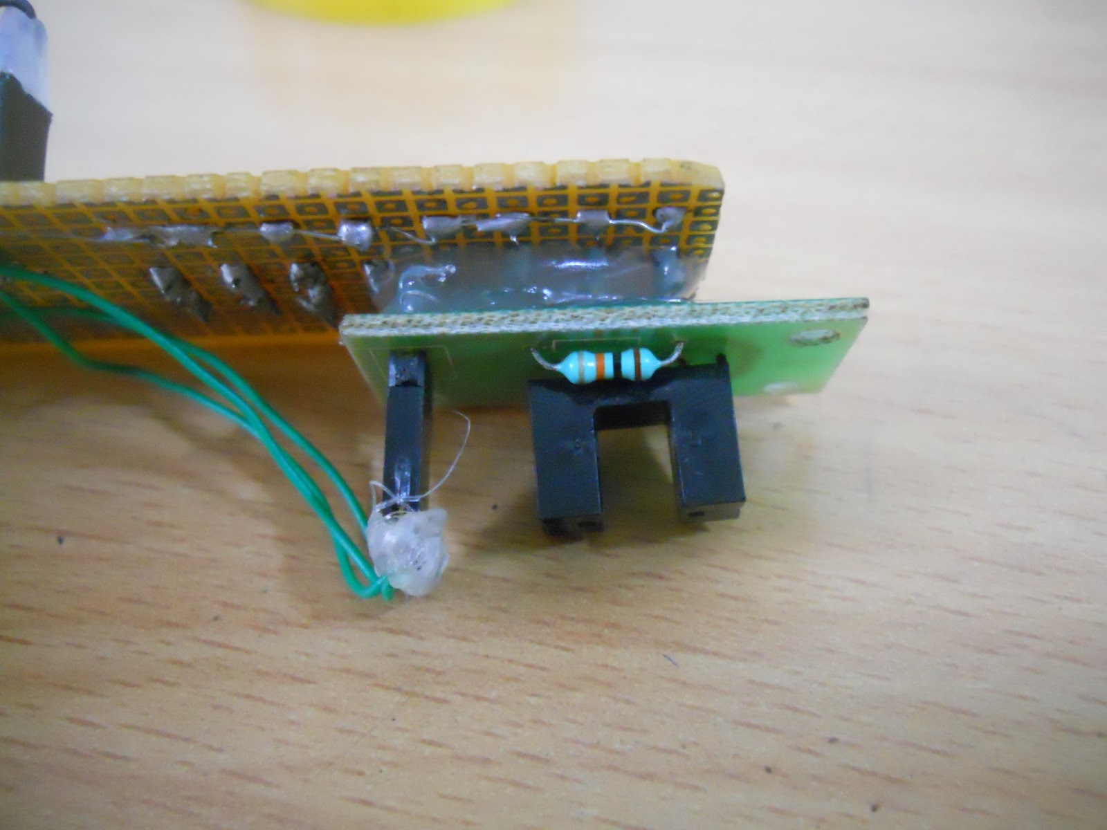


observe this video carefully.... you will find a small yellow paper on the base ground which comes in between the slot sensor pins and triggers the display. So your display always starts from a particular point
propeller LED display on sealing fan


the video:
Bluetooth controlled rotating POV LED display
ALL THE BEST
+++++++++++++++++++++++++++++++++++++++++++++
=============================================
NOTE:
DON'T JUST ASK FOR THE ENTIRE CODE.
TRY TO
DEVELOP IT FOR YOUR SELF
GO THROUGH THE ARTICLE ONCE AGAIN
YOU
WILL FIND EVERY THING
+++++++++++++++++++++++++++++++++++++++++++++
=============================================
=========================================================================
=========================================================================

=========================================================================

FOR THOSE WHO WANT TO BUY THE KIT:
FREE SHIPPING ALL OVER INDIA
MAIL US AT
vaabrobotics@gmail.com
FREE SHIPPING ALL OVER INDIA

313 comments:
«Oldest ‹Older 1 – 200 of 313 Newer› Newest»inspirable one
hai. its super.plz will u provide circuit diagram and program
thanks for visiting the blog
i developed the code for AT89S51 and atmega16
which code do you need
but soon i will upload the circuit(i need to make it in eagle)
nice work, bt wht sud i have to for inserting a analog clock...???
n how to calculate a proper delay, if my mmotor is of 150rpm??
please replay on my email is sonuverma.ece@gmail.com
according to persistance of vision the naked eye can only sence a continious picture illusion if it is faster than 1/16 of a second.to create the illusion one must use motor not less than 1000RPM
while calculating the delay you need to consider the radious of rotating arm,speed of motor,width of letter to be displayed
Good Work, I am bachelor in Mechatronics Enng., I need a favor from your side. I am working on a project on Speed control of AC motor by 8051 Microcontroller, in which motor starts,then i required to reduce the speed of motor after 10 sec. and it would stop around 14 sec.
very good job. can you provide the circuit diagram and the program for atmega16?
helo,am working with the same project.so,i neeed source code for ATMEGA16 micro controller...i need this urjent.so,plz help me as soon as possible my
Email id-bharshasai@gmail.com
hey can u plz send me the code for atmega16.......
shahsharad32@yahoo.in
hey can u snd the code of both microcontrollers...........
if so plz send to kukunurumanisankar@gmail.com
hello sir. . can you send to my email what are the materials needed for this project. ASAP plss. . avengemig@gmail.com Thank you sir
the material is simple
LEDs,resistors
a motor faster than 1000RPM
any microcontroller of you choice and required components like crystal,pcb,ic bases, capacitors.
on board power supply
and some mechanical parts to make the a stable rotation
hello sir i want to connect IR sensor for automatic interrupt so i dont hav to set delay and so wht r the modification u suggest.
if you are using 8051 you can connect it to INT0 or INT1 pins
and enable the corresponding enable bits
write the display in interrupt service routine
if you use ATmega16 or ATmega8 as the CPU is very faster you can just use "if" statement.
if(PIN==value)
{ display code
}
else
{
make some other function
}
what crystal are you saying sir? is it optional or its required for this project?
another one sir. . what kind of pcb is your using?? im not familiar of pcb. .
sir?can you send to me the circuit diagram and a tutorial how you assemble it. . i need some clarification of the "on board power supply". . I nedd it asap . .i hope you can help me here
you need to use 12Mhz crystal for 8051 it is a must
in case of atmega16 you can use internal 8Mhz or external 16Mhz
get any basic circuit of any microcontroller of your wish and connect 8 LED s to any port and as per the port make some modifications in the code
first study the basic concepts of any microcontroller nd proceed
on board power supply means we use dc battery.
we cannot use adopters from power sockets.
i used a 9v battery and 7805 voltage regulator
to provide 5v supply to microcontroller
i am using ordinary universal PCB of 2*3 size
check the figures in the article
arrange LED s on a small separate PCB
Guys please respect the author. I could see many of you asking certain redundant things when he has written it clearly what is the most necessary or the crux. So please stick to asking clarifications on things that have not been covered.
Vamsi, I really feel honored to have seen your blog. Really a great article. You made me feel the complex rocket science to be a mere a butter cutting with your code. Thanks a lot Vamsi.
But I need a clarification. What do these hexa integers mean ?
0x6f
0x81
Are they only the on-off states or do they point to the port number. Consider I am using the ATmega16.
Regards,
Ashok Srinivasan
you are right
they are just on off states of LEDs
refer to the example letter "A"
in the beginning i defined port P0 of 8051 MCU as "led"
because if you want to change the port it will be essay
for ATmega16 you can define any port as your wish
for example PORTB
#define PORTB led
#define DDRB out
out=0xff;//making all pins out put
led=0x81;writing led on/off sequence to PORTB
Vamsi,
I again want to clarify something. Suppose you are setting the value any of the pins of a port(A,B,C or D) to be used for character printing then for the Character 'A' the mapping is (for your 7 x 5 (rows x col)) should have been
column 1 - 0x7E;
delay_column();
column 2 - 0x90;
delay_column();
column 3 - 0x90;
delay_column();
column 4 - 0x90;
delay_column();
column 2 - 0x7E;
delay_column();
(the above is a simple pseudo code and not the actual one so please do not mind it)
Don't you think as per your character mapping of A?
Regards,
Ashok Srinivasan.
helo sir thx for previous rply i made hardware for project success fully n i write code also i am using 1000 RPM motor but my word are stretching can u tell me how much delay should i use to achieve output lyk urs.
can u please email me the code and the circuit diagram please i really want to makde this cool project ..
luman_united@yahoo.com
please refer to the article there you can find the delay calculations for 1000 RPM motor
but at real time the speed of motor may not be constant so first make the working model and calculate delays as per your model but the logic for calculating delay will be the same
i uploaded the example code you have to make your own code as per the LED arrangement
my code may not work on your hardware
sir u hv explained everything very nicely...bt i m confused how to attach motor with pcb...i means it must rotate..so how to do that??? nd next thing is cn u plz mail me the cicuit diagram on hardikamangukia@gmail.com...its my current semester project to make propeller clock...cn u gv me some ignition for c coding for atmega16 to make this propellor clock???sir plz plz plz help me nd rply soon as i hv to submit the circuit diagram on 9th August,2012..i wud be very grateful to u for ur help...
the circuit is similar to a "light chaser project" published on "Electronics For You" magazine.
but the main logic is to to arrange them on a rotating shaft
if possible you can also arrange the circuit on a "TABLE FAN" wing
but make sure that the fan is rotating at some low speed level step.
or else just watch the side view picture of the project in the article
i recommend you to go through the article again for the logic and code
wow..a great project.now, i'm working with this project. can you send me the schematic and design for both atmega16 and AT89S51.
this is my email zero_shin@yahoo.com.
Cheers
please don't ask for the circuit just like that
every thing was given in the article
please go through it first and then ask about your doubt
in the beginning i took 2 months to understand this concept
after referring the data sheets of all devises it became child's play
for beginners i prefer to get basic knowledge of any one microcontroller(8051 or AVR )
then you will easily understand every thing written in this article
ALL THE BEST
hey could u mail me the ckt dia of it. its really interesting to make one of these. mail me at suryadevmahto@gmail.com thanks :)
plz tell me the month in which magazine (electronics for u)has published about light chaser project...so i can read....thanks
i like your project...and i want to make my final year project on propeller led display using ATMEGA16 . plz tell me the month in which magazine (electronics for u)has published about light chaser project...so i can read....thanks
u can contact me via smilesagar2005@yahoo.co.in
light chaser is nothing but an 8 LED array connected to any port of any microcontroller.the LEDs are connected in active low mode.soon i will upload the circuit you will get an idea
hi am doing this project..how power supply is given for motor ,microcontroller ?...and where interupt is placed for ir sensor
you can use 12V 500mA DC adopter for powering the motor
for the MCU use a 9v battery with 7805 regulator
if you want to use interrupt using IR sensor connect it to INT0/INT1 pins and write the display function in interrupt service routine.
active low
led on ===0
led off ===1
can yo pls send me the pcb design for this project
how to calculate speed of the motor
for this kind of projects better make your own circuit on a universal PCB
speed of the motor will be given in it's data sheet
hello..i need the code for atmega16 for analog propeller clock i am thinking to take the output of RTC for the clock values..reply how can i do dis.?
can i use cpu fan for motor
pls reply soon
yes you can
but the problem is the fan may rotate at 2000rpm or more
cannot provide enough torque
Hii.. I am making the same thing. with P89V51 and 1000Rpm motor of Vega robotics as u suggested. please can you provide me the coding for displaying 'ckpe'? I need it really urgent. If you can please email me at nirmit09@gmail.com
I have already implemented the circuit. I just need the codes. please.
the over all algorithm for writing the code is made according to my circuit and and LED arrangement on the rotating arm.
so take a look at the example letter 'A' and my arrangement and try to develop your own code for it
it will be very simple
check the following
=>logic of led(active high or low)
=>arm length and motor speed
=>position of led(MSB LSB)
Thank you.. I analyzed your code and Developed my own code according to the need. At first the delay wasn't proper, so took a while to figure out exact delay. Finally, I completed it and my Professors are happy for it. Thanks once again.
im very happy to here that
keep on doooooing
the program that u have displayed above is showing syntax error ..... plz help...
yes
i know that it will show errors
because it is not a ready to use program
it will give you the basic idea to make your own program
i gave it for 8051 and ATmega16(AVR) micro-controllers.
which is yours?
what compiler you are using ?
before going to the code i suggest you to go through the article once.............
ALL THE BEST
Pls send me the circuit diagram pls
can you provide the code for propeller clock using 8051
go through the article once again
you will be able to find answers to all of your questions
Sir I am the student of EC Eng.from Gujarat. Its really nice work....i was searching this type of work since 2 months but today i find your blog.........and i hope it will very helpful to me...Thank u sir for the code and circuit diagram,, My question is "Is the simple DC motor from old tap-recorders can be used ?? Reply me soon.... i want to work on this project......
yes it will work but the problem lies in it is it is not easy to mount the circuit on it
if you can manage the mechanical part of it
then it will be perfect
ok sir thank u very much for your reply... can u exactly tell me that which motor you had used?? so that i buy it from the shop as u tell me its name,,, and in your example program in keil i found some errors.. can u resolve it???
Thank u
i used 1000RPM metal geared DC motor with 6mm shaft
this is available on vegarobokits you can get it from any hobby shop
OK sir thanks........ one another question...please check a programme once i got an error.....and i m not able to resolve it........can u do this???
Sir i am finding this project since 3 months......on your blog i found it......... i had started work for this project from one week....but i am getting failure and failure......i had made hardware and software as u suggest but i found only failure...can u help ?
i had made program for six letters but out put is only for 4 letters... i want to write Bharat but "Bhar" is displaying.........whts the problm of tht?
the motor speed will be the problem
you have to identify proper "Delay" for displaying your letter according to your motor
you need to calculate the maximum number of letters your arrangement can display. in which the length of the rotating arm will decide this
just go through the calculations
ok sir...........one more question? the length of the rotating arm should be long or short???for displaying more letters???
can you plz provide keil microvision code?
and the logic for clock.
more the length more the letters
my Shaft is around 5 or 6 C.m .......... It is sufficient???
pls snd it to me if u got it.. :)
usman_islamian12@yahoo.com
6 cm
so the circle perimeter will be 2*pi*r=13.6 cm
if each letter is 2.5 cm total letters will be 5
radius=length between center led to rotating center
Oh.my god.... you are mind blowing sir......... heads off to u......Thanx for replies..and ur guidance...... i exactly measure radius= 7 c.m.. and for that i had put delay as below..
void delay()
{
for(i=0;i<=10;i++)
for(j=0;j<=50;j++);
}
and this will displaying only 4 and a half letters..
the delay function will decide the width of the letter
as no two motors are similar i prefer you to calculate your own delay
or you can do one thing
connect a pot to ADC and ADC to microcontroller for 8 bit you will get 0 to 255 value use it for the delay. don't forget to keep this function outside the while() function.
the if you want to change the delay press the reset and change the pot
ok sir..........sorry sir but i can't understand about u say. "pot" u mean to say a motor? i have to connect motor to ADC and ADC to 8051 right? and this arrangement on the propeller shaft??
ok sir i understand... POT means Potentiometre right??
and sir can u just check or examine my video? i had made propeller display and upload on youtube....... can u just check that video for suggestion and improvement if u have time ??please?
next time dont forget to post the link
nice work buddy
try to increase the length of rotating arm
i prefer to start with AVR microcontrollers
because you can do more with them
try for ATmega8L microcontroller less size with on chip ADC channels
http://www.youtube.com/watch?v=BLVOzSRRL2k
this is the link sir..
yaa
i searched it in you tube and saw it
good
try with avr
Thanx for ur blog, ur guidance and ur positive replies sir.........
Can I have your mail ID sir for communicate adequately........??
I had tried the shaft radius to be increased but i didn't get more letters only 4 letters are displaying...........with 25 c.m lentgh
just change the delay...
so letter width changes
Sir What the Value Of DELAY u kept in ur program?? Where u wrote ("VAMSI ECE")
sir this is my Program format.......please take a look...... Is there any mistake in program?? because only 3 letters are displaying...
#include
#define led P0
void delay(void)
{
unsigned int i,j;
for(i=0;i<17;i++)
for(j=0;j<50;j++);
}
void main()
{
{
led=0x00; delay( );
led=0x6e; delay( );
led=0xff; delay( );
led=0x7e; delay( );
led=0x6e; delay( );
led=0x66; delay( );
led=0x91; delay( );
led=0xf7; delay( );
led=0x7f; delay( );
led=0xdd; delay( );
led=0xef; delay( );
led=0xf3; delay( );
led=0xff; delay( );
led=0x66; delay( );
led=0x91; delay( );
led=0xf7; delay( );
led=0x7f; delay( );
delay( );
delay( );
}
}
first thing :better to put comments in your code
second: better to use a function to display a letter
i used a function display('A'); to display letter
if you develop your code for such function
finally don't forget to put comments next time
What the Value Of DELAY u kept in ur program?? Where u wrote ("VAMSI ECE")
there is no proper standard value for delay
we need to use a random delay on your motor and correct it like trail and error method
This is the complete program as u say sir
#include
#define led P0
void delay(void)
{
unsigned int i,j;
for(i=0;i<17;i++) //Variable to control
for(j=0;j<50;j++);
}
void display(unsigned char car);
void main()
{
while(1)
{
display('B'); //display B
display('H'); //display H
display('A'); //display A
display('R'); //display R
display('A'); //display A
display('T'); //display T
}
}
void display(unsigned char car)
{
{
switch(car)
{
case 'B' : // letter B
led=0x80; delay( );
led=0xB6; delay( );
led=0xB6; delay( );
led=0xB6; delay( );
led=0xc9; delay( );
led=0xff; delay( );// to make one column gap between letters
break;
case 'H' : // display H
led=0x80; delay( );
led=0xf7; delay( );
led=0xf7; delay( );
led=0xf7; delay( );
led=0x80; delay( );
led=0xff; delay( );
led=0xff; delay( );// to make one column gap between letters
case 'A' : // letter A
led=0x81; delay( );
led=0x6f; delay( );
led=0x6f; delay( );
led=0x6f; delay( );
led=0x81; delay( );
led=0xff; delay( );// to make one column gap between letters
break;
case 'R' : // letter R
led=0x80; delay( );
led=0xf6; delay( );
led=0xf6; delay( );
led=0xea; delay( );
led=0x9c; delay( );
led=0xff; delay( );// to make one column gap between letters
break;
case 'T' : // letter T
led=0xfe; delay( );
led=0xfe; delay( );
led=0x80; delay( );
led=0xfe; delay( );
led=0xfe; delay( );
led=0xff; delay( );// to make one column gap between letters
break;
}
}
}
perrrrrfecctoooo
you almost made it
just try diffident delay values
or else use ADC and connect a pot to it and manually adjust the delay value
i used almost 37 cm of shaft
now i am planning to display letters on sealing fan
once i made it i will upload it
im going to use ATmega8 microcontroller
Wow just great sir.......... All the best for it................sir
till now i made it for clockwise rotation
but the sealing fan rotates in anti clockwise
i need to reverse the letter format
lot of work..............................
okkkkkkkkkk sir...when u complete it must put its video... and if u want any small help i m ready to do it...coz i m very interested in this stuff.. thnk u sir..
had u used pull up resistors for PORT 0??
i had made and it outputs well... but how to stabilize the display..........it is moving continuously.. plz rpl
if you want to use it of input you must use pull ups
but for output no need of pull up
if you are good at microcontrollers
use interrupt concept
connect an IR sensor to INT0 of 8051 and write the display code inside the ISR(interrupt service routine)
it will be like if you interrupt the sensor then the display starts...
try this......so that you can shift the display manually
ok ... for ir sensor can i use TSOP or anything else???
hello..i need the code for 8051 for analog propeller clock i am thinking to take the output of RTC for the clock values..reply how can i do dis.?
yesssssssss i had made the display 100% stable using IR sensor and it works.....
congrats.....can you upload it on you tube
so that we can see it..
don't forget to share the link...
bro! do u have code of digital clock? if yes then plz..:) usman_islamian12@yahoo.com
hi sir i need the c code for it with interrupt INT0 .
must reffer this video link ..... animation through propeller display using interrupt....... thnx for ur help sir.......
http://www.youtube.com/watch?v=B8e5p1X8Cik
kshitij ..how to shift display left or right..i have seen your video its amezing..thanks
for shifting display firstly u have must to stabilized the display ....for that purpose interrupt is use... and by provide the number of spaces in a specific manner u can shift the display
propeller clock was great and i want to make it can u please send mail me its circuit and its code for atmega 16
and tell me is it necessary to connect motor with atmega
sir can u plz send me its circuit and andd atmega8 or atmega16 programing and alo tel me is it nessary to connect motor to controller or its only to rotate it
Hi..I am doing this project as my final year engineering project..I use ATMEGA16..plese send me program for ATMEGA16 at smilesagar2005@yahoo.co.in
TRY TO MAKE THE CODING ON YOUR OWN
Hello Vamsi....I had a little doubt .....
What is the working of the IR Sensor...?? And which one have you used...??
I thought that there should be an opaque object between the 2 slots of the sensor...but there is no such thing in the picture above which shows the attachment of the sensor to the pcb.....
Very Confused...!!
Hope you would help..!!
Thanks...!!!
take a look at the video
you will understand ......
it is a IR slot sensor (interruption sensor)
hello sirr... plz send me the schematic for atmega16 at ramsanjay83@gmail.com...
Hello Vamsi...
I was thinking of a different application based propeller display....
what if we give a input by means of a keypad...like the user is supposed to enter either of the buttons of the keypad and then we get a display according to that...each number having a fixed display associated with it...??
got any ideas..?
hope for the best..!! reply soon...
Thanks...!!!
this can be done
you need to store the data at run time and that should display even after the power loss.
you need to use an EEPROM...
8051 is not having any EEPROM
but AVR microcontrollers have on chip EEPROM
I am not getting...Can you please elaborate ...??
I want to do it in 8051...
I am confused....I am thinking of a concept in which when we press any button of the keypad then we get different displays on the propeller accordingly...
Pls help...
Thanks...!!!
hello sir .....
i want circuit components description sheet of propeller led ...
send me as soon as possible ...
email id:apjak920543@gmail.com
thanks..
hi sir, could you tell me how about the wiring of the power supply? I mean isn't there a chance of the wiring having a lose contact and coming in the way of the motion of the display? It would also be nice if you provide the applications in everyday life for such displays? thank you.
1)how about a 9V high watt battery and a 7805 regulator....
2) imagine you raiding a bicycle or bike..
with your name
on the wheel......?
hello sir .....
i want circuit components description sheet of propeller led a...
send me as soon as possible ...
email id:akaclark21@gmail.com
thanks..
I need more info on stabilizing the display. with your blog help i had made the display but cant stabilize it. What will be the calculations if i use opto-interrupter switch?. Shouldi take take of the delay all the time by calculating rpm of motor.
I have also mailed to mr. kshitj moni. Dear Friend please elaborate your work on stabilizing the display it will help us a lot. I am workingwith pic microcontrollers.
Also Vamsi sir i want to know what motor you have used and where can one find it. Also can one use ac exhaust fan motor or dc motor is best
you can use the motor in your PC
also called "DC cooling FAN"
and it will rotate in anti clock wise direction
and its good to here that you worked a lot on this project......
you said that your using PIC controller...
you can connect the sensor to any external interrupt pin(don't forget to check for active high or active low value from the senor)
make you ISR function in such a way that it contain your display routine...
don't directly go to the auto delay calculations using timers. i will confuse you.
first stabilize the display with any random delay. once you got the stable display then adjust the delay value manually in the program.
ALL THE BEST
please respond asap.I participated in a expo to be held at 17 feb .I wrote so many codes for pov and using the default delay function _delay_ms() made the hex file larger than 16 kb.so I can display a max of 3letters or size of hex becomes unprogrammable in atmega16.plz suggest sth.have been trying 2fix it but with no success.
thanks.
what.....
size is increasing....for only 3 letters
if your display is large enough
you can display like 100 letters even with an ATmega8 mcu
i need to check your code
mail me at vaabrobotics@gmail.com
Pratik Bhagat , i had seen your mail and replyed u just check it...... And Vamsi sir is absolutely right........... by the guidance of him i had achive the success in this stuff.........so.....
Hello VAMSI, i want to build this propeller clock using AT89S51, if you could email me the code at s.atayi379@gmail.com. Many thanks.
Hello Vamsi Sir, I am trying to to do the spinning display project.I m facing problem in Placement of batteries on pcb. if i do so the pcb is becoming heavy and wobbling while rotating. Also if I use IR led photo diode pair for external interrupt, its not being sensed by controller at high rpm(I am using 1000rpm motor). Which type of sensor I must use sir? and which type of battery shall i use to power up controller?
tell me one thing first...
what type of arrangement you made to rotate the display....
Hello Vamsi....
What type of slip ring have you used for the project for the power supply....???
Thank you..!!
can u please tell me how to use interrupt module.......thank you
sir, i m built a propeller circuit,but i have problem in program basically in delay calculation can anybody help me to calculation of perfect delay or that concept
Vamsi Sir, I'm having a problem in finding the motor with the precise specifications(rpm,torque) from the local Kolkata market.I am trying to use a 1000rpm motor.Can you suggest me where I can order for these motors? What kind of motor did u use for your Propeller LED display project and from where did u buy it?
hello sir,
sir i need to know how you use interrupt, and what you use for interrupt and also interrupt code.
please help me i have to submit my project at 20
and also send me more detail and circuit diagram on my email:- itsme.creative@gmail.com
thank you so much
Please reply me....soon
interrupt concept differs from controller to controller. so which controller you are using
8051 or avr.
4051
sir plz send me code with interrupt....for 89c4051
can u pls snd me the code for keil c using interrupt for at89c51....(for displaying any word)
mail id t.togis@gmail.com
sir it is possible if i connect it to gsm technology then the received message will be the display?? i plan to use 15 led's.
thank you sir..
mail:lat.melvin@rocketmail.cm
vamsi sir, i am working on propeller led display
and i successfully display the latter but its still unstable , i read whole article of you. you asked for slot sensor to use for stable the display . can you please help me that how to connect the slot sensor to the interrupt pin of the 8051.
please help me by showing the circuit diagram of slot sensor interfacing with 8051...
sir
pl send full detail about this propeller display to this email id keshavraj916@gmail.com
where is rpm related calculation in the theory i cant find it plzz help
if rpm is 1000 then time for 1 rotation must be 3.6ms isn't it???
Sir ,
Please send complete details with code about propeller display on harshal.chadha@gmail.com
hai vamsi danda,
u done a great job,
keep it up.
i have made many projects on atmega16...and today i found your project...sir please can u send me the codings for dis project on atmega16
@ VAMSI DANDA you should put the image of o/p of the program u have given for example..
as i under stand there will be a letter A first then one column gap then 5 column gap then again letter A..am i right??
I want to make this project but i should understand the logic first..
guys , i have been working on propeller clock using atmega16 but i cant display the time please check my code
#include
#include
unsigned char message[8]={'1', '2', ':', '0', '0', ':', '0', '0'};
unsigned char data[55]={
0x83, 0x7D, 0x7D, 0x7D, 0x83, //0
0xFF, 0xBD, 0x01, 0xFD, 0xFF, //1
0xBD, 0x79, 0x75, 0x6D, 0x9D, //2
0x7B, 0x7D, 0x5D, 0x3D, 0x73, //3
0xE7, 0xD7, 0xB7, 0x01, 0xF7, //4
0x1B, 0x5D, 0x5D, 0x5D, 0x63, //5
0xC3, 0xAD, 0x6D, 0x6D, 0xF3, //6
0x7F, 0x71, 0x6F, 0x5F, 0x3F, //7
0x93, 0x6D, 0x6D, 0x6D, 0x93, //8
0x9F, 0x6D, 0x6D, 0x6B, 0x87, //9
0xFF, 0x93, 0x93, 0xFF, 0xFF //:
};
void incmin();
void inchour();
void incsec();
void display();
void init();
unsigned int do_adc();
void display()
{
int i,j;
_delay_ms(100);
for (i=0; i<8; i++)
{
for (j=0; j<5; j++)
{
PORTA=data[message[i]*5+j];
_delay_us(95);
}
}
}
//**********************************************************
void inchour()
{
if ((message[0]==1)&(message[1]==2))
{
message[0]=0; message[1]=1;
}
else if ((message[0]==0)&(message[1]==9))
{
message[0]=1; message[1]=0;
}
else
message[1]++;
}
//******************************************************
void incmin()
{
if ((message[3]==5)&(message[4]==9))
{
message[3]=0; message[4]=0; inchour();
}
else if ((message[3]!=5)&(message[4]==9))
{
message[3]++; message[4]=0;
}
else
message[4]++;
}
//******************************************************
void incsec()
{
if ((message[6]==5)&(message[7]==9))
{
message[6]=0; message[7]=0; incmin();
}
else if ((message[6]!=5)&(message[7]==9))
{
message[6]++; message[7]=0;
}
else
message[7]++;
}
//******************************************************
void init()
{
ADMUX=(1<<REFS0);
ADCSRA=(1<<ADEN)|(1<<ADPS2)|(1<<ADPS1)|(1<<ADPS0);
}
//*****************************************************
unsigned int do_adc()
{
ADCSRA|=(1<<ADSC);
while(ADCSRA&(1<<ADSC));
return ADC;
}
//*****************************************************
void main()
{
// Port A
DDRA=0xff;
PORTA=0xff;
unsigned int adc_value;
init();
while (1)
{
adc_value=do_adc();
incsec();
display();
}
}
please help me ..rply as soon as possible
hello sir i need the whole circuit and program to display ADITYA.
please do help me out
Sir, i didn't get abt that interrupt n IR sensors why they r used n how they are arranged. how n when will be the interrupt routine will be start... plz explain..
to stabilize the display
it means the display starts from one position only
sir,
to start the project, do i need any more items other than the below mentioned ones???
1000 rpm dc/ac motor
8 leds
atmega 16
dotted circuit board
what must be the range of the crystal ossilator??
how many leds do i need if i am making a clock ?
what is the use of an IR sensor in your circuit.
The scope of the project is to design a display system using LEDs which rotate on a motor. The circuit is mounted on DC motor. LED'S are used to display clock and date. PICF84A is used to control and transmit the signal and utilizing the Assembly language.
The goal of our projects is to design a prototype of an enlarged version of the Propeller LED display for displaying message. After studying various techniques like matrix led’s, rolling displays, etc. which are also techniques of displaying message at the cost, therefore we choose propeller led display, an emerging technology applied for displaying message. The display consists of 7 LEDs only in a vertical row. By moving them fast enough back and forth over each other, message can be displayed which appears to be generated by a 7*n matrix of LEDs and not a single column of LEDs, where n is the no. of columns of the display matrix. The LEDs will rotate on a motor
The 9V DC is supplied to Motor Controller Circuit. Motor Controller circuit is controlling the DC motor speed and the speed is adjustable. In order to rotate the circuit, DC motor is used. PIC microcontroller purposed is to execute the program and transmit the signal to LED. As output, a line of LED is used to transmit the desired signal. In order to display the images,
please help me on this i need the schematics for the pcb and how i should go about powering it up ASAP.
hozala@gmail.com
hi..sir it ia a nice project ......but i did not understand one thing is motor wires connected internally in circuit or u r giving any external plug to it .........if u given internally please mention from where to where u connected sir and please send me code for AT89S52 HERE MY EMAIL SIR
mahi.raju.487@gmail.com
and u have written the program above for letter A .i understood but why u have written 2nd case program
hi i have a doubt .that is the above shown 'A' table 1ST COLOUMN IS 0*81 i.e all red colour marked are 0s and remaining white coloured are 1 that it .........please clear it why because for letter B,C,D...etcgot some values they are not matching with another codes in google ......
vamsi sir i dont understand where the code start and where the code end in your article so can u tell me plz this project i want to present in compition plz rply me soon.... plz reply on my email id harshal.inventor123@gmail.com plz.....
can u please give me future scope and conclusion of this good project
Hi sir,
nice project it is!! I built it but I have problem about coding. while compiling in keil u4 ,compiler show error for following lines
void delay(void)
{
unsigned int i,j;
for(i=0;i<del;i++)
for(j=0;j<1275;j++);
}
so I m not getting hex file..plz guide me,thank you.
you are saying it a good project ...........
future scope: write about where you want to use this
conclusion: write about the plus and minus points of the projects
hello shivjit
when ever you compile a code and got an error
read that error first
if you read the error then you can find it for your self
one cannot identify the error from just a part of the code
hello sir .. please provide me its circuit diagram and full detail on my email id,,, kapilgiri.ec2010@vitsgzb.com
i wana to make this project its so nice
sir how to calculate delay parameters in microseconds can u give brief detail
in your atmgea 8 circuit could u tell me what's the value of capacitor used. also cld u provide mw with the circuit diagram for atmega 8
is the circuit arrangement or both atmega8 n 8051?
Sir can you explain the interrupt using IR sensor for example IR led and photo diode. how does it works if we want to display a Digital Clock.
looks a great proeject
Hello Sir,
I would like to know more details about the components used like the resistor, capacitor values, etc. Resistor color coding exists for 220ohm but what does 220E mean ?? Reply as soon as possible. Anyone knowing about this doubt can clarify.
Thank You.
how to programar sir help me i like ur projct hex code atmega8 and programar v
hai ur project is good but i need the source code to display the clock can u send the code to my mail
vijay.shekar18@gmail.com
Plz mention the capacitor values...It is not visible...
in 1st circuit diag, u r using 18pf and next circuit diag u r using 33pf...which one is better...
actually capacitor value is not that important. But both capacitors must be equal
but in most of the cases 33pf or 22pf are preferred.
hello sir ,
u are very helpful .. thanks for guiding all of the knowledge seekers ..
sir i am also making this project ..
i am planning to use desktop pc cool fan .. and to calculate its rpm a pair of IR and TSOP transceiver (its rpm are unknown)
moreover i am implementing this circuit on pic16f877a microcontroller using 20 Mhz. crystal
my question is using high freq crystal and high rom motor will that be good or bad and
plz add on or correct me in my approach whereever m gng wrong
thanks sir :)
hello sir! for so long i am searching for ots supplier in india.........can v take this prjct as the major one..........bcoz i want to make one for my final project submission ........sir pls do tell which microcontroller i should use...........8051, avr or pic...........sir can u pls provide stepwise circuit design......its program..........using 8051..............n sir shld we consider this as a MAJOR one............i dont want to make a propeller clock using RGB leds displaying images and time.both analog n digital as well......................................................sir pls help me out.......................n seriousy u hav dne a g8 job............thks
hi sir i am studying final year ece i searching this project i found this blog is very helpful from today i am starting my project by using 8051
hai sir i used micro vision 2 for prg but i get that unkown device , whats the prblm was? plz suggest me
hello dear sir please give me atmaga8 avr code this project i'm very thankful to u
Email: jugjeewan@gmail.com
sir plz tell cristal hz for atmega8
sir i didnt understand code terms
led=0x80; delay( );
led=0xf6; delay( );
led=0xf6; delay( );
led=0xea; delay( );
led=0x9c; delay( );
can u plz explain it sir..........
im using internal 8Mhz crystal
those statements display 5 columns of led on patterns with each column life time=delay();
can i write that program by my own like PORTB=0b01111110;
_delay_ms(50);
yes you can write that statement
but the delay that you write must be calculated
for POV display _delay_us(); function is preferred more..
check the delay calculations in the above article you will find out
for displaying "A " is it is correct and what is different between _delay_us()and _delay_ms()
#include
#include
int main(void)
{
DDRB=0b11111111;
while(1)
{
PORTB=0b00111110;
_delay_ms(50);
PORTB=0b01001000;
_delay_ms(50);
PORTB=0b01001000;
_delay_ms(50);
PORTB=0b01001000;
_delay_ms(50);
PORTB=0b00111110;
_delay_ms(50);
}
}
Very nice sir...this will spark me enough to do it at my own
Its a very Nice Project Sir. I appreciate U ve thrown a lot of light on the detailed procedures. I even tried it n got a bit of success. But the area where am actually facing the problem is, I am unable to understand the logic to display different characters. I ve seen the above example for character A using the table u ve mentioned. but am not getting it. can U please elaborate the process, for displaying different characters
Excellent post! Thanks for this great info. Nice share!
Led Display
Very good project mr.vamsi danda.i done the same project to display a message but it is not giving the accurate dispaly of message "letters are not diplaying in a particular postion at one instant some letter is in some x position,same position is replaced by some other letter after some time" i am facing this prob so please help on this and if you don't mind send the relevent data on pawankumarkodali@gmail.com this mail....
hello pavankumar
to achieve perfect POV display the rotating module must be accurate and you must use perfect delay
instead to stabilize the display you can go for IR interrupt sensor check the picture
hello sir, ur blog is really helpful, but actually my purpose is a long time running propeller led, and for tht it is not feasible to use a 9v battery power supply, so i ned to supply power directly from ac mains, so can u give me solution regarding how to provide power to the rotatory circuit...i have read many articls saying slip rings and all but actually i am not getting a proper slip ring as i m using a normal dc motor of 1000 rpm having its shaft length around 25 mm only..so can u suggest some remedy please, or contact of some vendors who could help coz i m a fresher in this field and i need help..thank u sir..pls do reply me on my mail if possible...nabilkarimi92@gmail.com
I am also trying to build an 8051 led propeller clock what of motor do you honestly suggest that i should use could you email me at rigo0925@live.com
Thanks
hello nabil karimi use wireless power transfer technique to send power wireless use inductive coils...
hey rigoberto
choose the motor according to your display circuit length and weight check the pictures in the post ....
Thank u sir.....such a great work.
thanks and i have one more question did you buy your development board to program the 8051 or did you make yours?
most of the time i make my own
Glad to see the post.It's awesome.Great idea use in this project.Really remarkable.Thanks for sharing the post.
http://lednsign.com/
thanks for idea dude.. i was thinking about the power supply for circuit. now this will be easy to place on board power supply using battery, and mounting on cpu fan is vary good idea,
again thanks
Post a Comment