Sunday 13 March 2016

DHT11 humidity and temperature sensor interfacing

when i first got this sensor in my hand i thought it might be an analog sensor and tried with analog channels which dint work.

Then after googling some time i found a data sheet saying this sensor works on 1 wire interface which means a single microcontroller pin used as both trigger and input reading.


This sensor provides 40 bits of data in a single burst.

8 bits humidity data integral part.
8 bits humidity data decimal part
8 bits temperature data integral part.
8 bits temperature data decimal part
8 bits check sum data

 There is a data frame sequence to be followed to read the data from this sensor. I copied these frames from its data sheet.

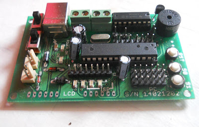
So got the data frames are ready. My choice of microcontroller is ATmega8 as i got an awesome USB programmable development board with me.
Good support drivers provided with this board like lcd, uart, adc all in winavr compatible C.
I am using PORTC pin PC0 an sensor data pin.


here is the code:
//============== start of program=================================

#include<avr/io.h>
#include<util/delay.h>
#include"uart.h"// UART header file provided with the development board
                          // serial communication

unsigned char temp=0,humidity=0;// actual values
unsigned char hm_bit_count=0;// count the 40 bit sequence
unsigned char hm_pulse_width=0; // to identify the pulse with in case of '0' and '1'
unsigned char hm_data_buffer[50];//40 bit sequence

void main()
{


 uart_init();// configures the UART value
_delay_ms(100);

while(1)
{

 DDRC=0x01;//PC0 out put
PORTC=0x01; //PC0 high
_delay_ms(10);// 10 ms high for stable value

PORTC=0x00;//PC0 low
_delay_ms(18);//low delay trigger to sensor
DDRC=0x00;// PC0 input
PORTC=0x01;//PC0 internal pull up enable
_delay_us(2);//input mode and pullup 20us wait min(i kept 2 instead of 20 )
while((PINC&0x01)==1);//wait untill the sensor pulls the line to low
  while((PINC&0x01)==0);//wait during the line is  low for 80us
  while((PINC&0x01)==1);//wait during the line is high for 80us


// reading sequence starts

    for(hm_bit_count=0;hm_bit_count<40;hm_bit_count++)//reading sequence of 40 bits
{
      while((PINC&0x01)==0);//wait for 50 micro sec delay before bit

      for(hm_pulse_width=0;hm_pulse_width<80;hm_pulse_width++)//max width is 70
    {
 if((PINC&0x01)==1)//pin high
  _delay_us(1);
  else
  break;
     }

  if(hm_pulse_width>40)//if width is 28us then 0 and is 70 for 1 so im using 40 as threshold
          hm_data_buffer[hm_bit_count]='1';// storing character 1
else
hm_data_buffer[hm_bit_count]='0';// storing character 0

}

 tx_string("\n\r raw data: ");// display function using UART
 tx_string(hm_data_buffer); //displays the buffer values


  temp=0;humidity=0;

// i am considering only integral part of humidity and temperature values.

  for(hm_bit_count=0;hm_bit_count<8;hm_bit_count++)// converting raw bits to single byte value
  {

   if(hm_data_buffer[hm_bit_count]=='0')
   humidity=(humidity&0xfe);
   else
   humidity=(humidity|0x01);
   //if(hm_bit_count<
   humidity=humidity<<1;
  }

   for(hm_bit_count=16;hm_bit_count<24;hm_bit_count++)
  {

   if(hm_data_buffer[hm_bit_count]=='0')
   temp=(temp&0xfe);
   else
   temp=(temp|0x01);
   //if(hm_bit_count<
   temp=temp<<1;
  }

tx_string("   humidity: ");tx_num(humidity);
tx_string("   temperature : ");tx_num(temp);

}//end of while
}//end of main
//============== end of program=================================

NOTE: in the above program i just omitted the decimal part of the sensor data and displaying only the integral part of them.

In order to display the values on PC i'm using CP2102 usb to serial converter and tera term software at 9600 baud rate.

Friday 11 September 2015

ESP8266 wifi module Basic working circuit and AT commands

I have been waiting to buy this module for 8 months..and i got one finally..when i'm testing it for the first time i faced lots of problems. after lot of googling and 2 continuous sleepless nights i figured it out..and felt lot crazy about the mistakes that i made while checking  ESP8266 module is little tricky compared to the other famous wireless modules  like Xbee or HC-05.

So i wanted to share all the problems i faced during my first successful test of ESP8266.

Beauty of ESP8266 :

This is simple small wifi module that is very much simple and so cheaper than a Bluetooth. I bought it for  Rs 400/-. 

The best thing is it is Serial UART interface which is basic feature in many Microcontrollers....

It is also equipped with GPIO(General Purpose Input Output) pins so you can directly use this module to switch some leds or any digital controlled devices with out a Microcontroller..  

identifying the circuit

So the first thing in our mind after getting this module is about its pin configuration.
The above version is abundantly available  in the market. It contains 8 pins arranged in two rows.
3,3V and GND are for power supply
GPIO0,GPIO2 are i/o pins which are programmable
RST  is reset signal for module(beginners better not use it) 
CH_PD : power down mode enable(to enable chip we need to connect it to Vcc)
Tx, Rx are serial Transmitter and Receiver pins.

along with these pins another two important things are Power(RED) and N/W(Blue) LEDs.

Supply voltage Vcc  for this ESP8266 module is 3.3V  
if you are using an arduino you will find 3.3V on arduino to run the module.
if you are using any other Hardware that run on 5V then i suggest the following circuit using a asm1117 3.3v voltage regulator..
Middle pin in the above module is also 3.3V o/p. For circuit convenience i prefer to go for notch instead of the pin.This voltage regulator provides upto 800mA current at 3.3V which will be sufficient to drive ESP8266. Do not forget about the capacitors(i used 10uF) in input and output of voltage regulator. 

The CH_PD pin should be connected to Vcc to keep the module in active mode. if this pin is not connected to Vcc your device will be in ideal mode and will not work.

As the Rx and Tx pins of ESP8266 are working at 3.3v logic levels, if you connect a microcontroller working at 5v vcc this module then there is a chance that ESP8266 may get damaged.

To protect the Rx pin of ESP8266 connect a 300 Ohm resistor in between
                             Rx(ESP8266) to Tx(microcontroller)
But there won't be a problem with Tx(ESP8266) as it can be directly connected to Rx(MC)

so the simplified circuit is :
   
   My prototype.

To test the module through AT commands there are so many serial monitoring software are available for windows. even ARDUINO serial monitor can also be used. I am using a serial terminal monitoring software called " Tera Term " .
Tera term support both Serial and TCP/IP.

i am using CP2102(USB to Serial) and TeraTerm to check the AT commands.


Saturday 8 August 2015

AVR Embedded Systems Workshop


AVR Embedded Systems Workshop


AVR Embedded Systems Workshop mainly focuses on the students and hobbyists eager to learn about Advanced features of AVR Microcontroller. They will get a chance to expand their knowledge in interfacing LEDs, GPIOs, Potentiometers, LCD Display and their application in real time projects.

The duration of the workshop will be one day with 8 hours hands on practical session. Each person will be provided with the non-takeaway AVR kit for hands on.


1. Introduction to Microcontrollers
   
          This session would deal with the basics of Microcontroller. the focus will be on the AVR series micro controller - ATMega8, which is one of the most powerful and widely used 8 bit micro controller.

2. Introduction to Software and Debugging

          This session would deal with the basics of 'Embedded C', writing your First 'Embedded C' program in AVR studio. Program compilation and Loading compiled C program into the microcontroller.

3. Input and Output (I/O) operations
          
           This session deals with Interfacing LEDs, Switches to the GPIO pins and generating LED pattern using switches.

4. ADC operations 

          This session deals with Interfacing Potentiometer to the ADC input of the AVR micro controller and hands on performing operations like controlling intensity of the LEDs by reading potentiomenter data.

5. Interfacing DC motor

          This session deals with Interfacing DC motor to the AVR microcontroller and hands on performing operations like operating Motor speed and direction control.


Note: The kits provided at the time of the Workshop are non-take away kits (you have to return the kits at the end of the session).

Note: Images for representation purpose only

Location:  Bangalore

For more Information like payment for workshop, mode of payment, Venue, scheduled date

with subject "AVR Embedded Systems Workshop"


Tuesday 4 November 2014

HC-05 Bluetooth AT commands configuration


We have been using the serial SPP(Serial Port Profile) Bluetooth modules to interface our embedded hardware and robots to Laptop or a smart phone... hear is an example of Bluetooth controlled POV LED display and a smart phone turned into an intelligent robot....


So this HC-05 is very much useful if you want to make some thing cool like this. So it will be helpful if we are aware of the configurations commands to work with the module. 

AT commands:

AT commands stands for attention commands with which we communicate with the module and alter it's performance.

There are TWO modes of working with HC-05 module. To check with the module you will need a serial port on your PC or laptops. But nowadays our PC won't come with an inbuilt RS232 serial interface  so you can use any USB to serial converters like CP2102 or FT232 devices. After connecting the device to the PC we need any serial terminal software in case of  windows7 and 8 like "Teraterm" or "Putty" .But in case of windows XP you got hyper-terminal. 

In my case i got a CP2102 with me. connect Bluetooth to the CP2102 UART pins (RX and TX)

  
 There is one important thing that you need to keep in mind is....
 "your Bluetooth module logic voltage levels" mine is 3.3V but it got tolerance up to 5V so no problem with my device. and my CP2102 is direct TTL and I am not using any MAX232 in this. so make sure of your device before powering it.

 after connecting the Bluetooth to your serial port device like the one in the picture above. 
connect the device to your PC and power it up...now you will see an LED blinking very fast on your Bluetooth module. This is the normal serial data mode.

Now remove the power. Press and hold the mode button and connect the power. Then the LED will start blinking very slowly...which indicate that you Bluetooth is now in "AT command"mode.

open the serial terminal software and select the "COM" number of your serial port module and configure the following                                
baud rate as"38400"
hardware    "none"
parity          "none"
databits       "8"
stop bits      "1"

better enable local echo in your terminal software...

type "AT" and press <enter> switch you will get response "OK" it means your device is working in AT mode successfully..once if you disconnect the power then the you Bluetooth will be back to serial data mode.

NOTE: in AT mode the baud rate will be 38400. but in serial data mode many baud rate values can be  used.

few of the useful AT commands:

AT    <enter>   it gives the response OK continuously so press <enter> again to stop

AT+NAME?  <enter> it displays the name of Bluetooth module

AT+NAME=new_name  <enter> changes module name to "new_name"

AT+PSWD?  <enter> displays password to enter while pairing with this device

AT+PSWD=4321 <enter> changes the password to 4321
( only 4 digit number is accepted as password )

for more info regarding AT commands refer to the data sheet.


Thursday 3 July 2014

PIR motion sensor interfacing with microcontroller


Passive InRrared sensors:


This sensor senses the bodies that emitting IR radiation and are in motion. there are several types of PIR sensors are available in the market. most common types are these TWO..


TYPE.1: with one potentiometer                                                                                


 This Pot is used to set the time of out put signal  stays at logic high on object detection width. this  sensor's sensitivity can't be altered. It produces a     3.3V "logic high". 


TYPE.2: with two potentiometers  
The device has two variable resistors that you can adjust to tweak the performance of the module.
The first one (left-hand side on the photo) determines the sensitivity of the device. The default setting is usually 50%.
The second control (right-hand side on the photo and usually marked “time” on the PCB) allows you to adjust the amount of time the output pin stays at 3.3V (high) when it is triggered by movement. This can be set from a few seconds to 200 seconds. The default setting is usually a few seconds.
    WORKING:
But the operation of the both sensors is same. This PIR sensor doesn't respond for the stationary objects. Instead it senses the IR bodies in motions(hot materials and living objects). This sensor accepts DC voltage of 5V. 

NOTE:

Most of the time pin configuration will be printed on the sensor . But some sensors available with in in India are not describing pin configurations properly. But the standard notation of pin will be like all ways middle pin will be output. so if you identify the GROUND then remaining pin will be VCC.
It is very simple. Most of these sensors are made of using BISS0001(16 pin DIL package). 7th pin of this IC is GND. So take a multimeter and  check for short circuit test and beep sound. then it will be your sensor ground and opposite side pin will be VCC


As the sensor provides 3.3V signal it may be little difficult to interface with microcontrollers working at Vcc=5V(most 8 bit hobby controllers like AT89S51). At the same time it will be easy to interface with low powered microcontrollers like LPC2148. You better check your microcontroller Logic voltage levels.


Actually i interfaced this sensor to ATmega8 MCU which can detect even 3.3 volt logical signal. So i successfully connected this PIR sensor to the ATmega8 microcontroller.

Basic Program 

#include<avr/io.h>
void main()
{
  DDRC=0xfe; //configuring PortC pin 0 as input
 PORTC=0xff; //enabling internal pull-up resistors
DDRB=0xff;    // configuring PortB as output
PORTB=0x00; // buzzer off

while(1)
{
  if((PINC & 0x01)==0x01) // check for sensor pin PC.0 using bit       {                                            //masking (if sensor detects motion ) 
   PORTB=0xff;                   // buzzer on
   }
  else
  PORTB=0x00;                   // buzzer off
}

}
   

Tuesday 13 May 2014

Bluetooth controlled robot using ARDUINO

This article helps you to make a robot that can be controlled from your android powered mobile through Bluetooth.


 HC-05:

This Bluetooth module works on SPP (serial port profile). It establishes a serial communication(UART) between your android mobile and microcontroller.

This module works in two modes:
1) AT mode
2)COM mode

AT mode:

In AT mode you can directly connect the module to your computer hyper terminal or any other serial gate way through DB9 serial port through MAX232 circuit (or you can use any USB to UART gateways like FT232and configure through AT commands. set the baud rate "38400"
some example commands:

AT    <enter>   it gives the response OK continuously so press <enter> again to stop

AT+NAME?  <enter> it displays the name of Bluetooth module

AT+NAME=new_name  <enter> changes module name to "new_name"

AT+PSWD?  <enter> displays password to enter while pairing with this device

AT+PSWD=4321 changes the password to 4321 ( only 4 digit number is accepted as password )

for more info regarding AT commands refer to the data sheet.

COM mode:
this is the mode that to be set when interfacing with a microcontroller through UART.

In this project i'm using an Arduino MEGA 2560 and a Bluetooth shield from Robogenesis

To drive the DC motors i'm using L293D.

CIRCUIT DIAGRAM:


arduino code:

//---------------------------------------------------
//--------------- code starts-------------------------
//---------------------------------------------------
unsigned char blue_data;
void setup()
{
  Serial.begin(9600);// set up serial communications with 9600 baud rate

  pinMode(7, OUTPUT);//motor 1a
  pinMode(6, OUTPUT);//motor 1b
  pinMode(5, OUTPUT);//motor 2a
  pinMode(4, OUTPUT);//motor 2b
digitalWrite(7,LOW);
digitalWrite(6,LOW);
digitalWrite(5,LOW);
digitalWrite(4,LOW);
}

void loop()
{
   if (Serial.available() > 0)
  {
    blue_data = Serial.read();// get incoming byte from bluetooth
          if(blue_data=='F' )//forword
           {
            digitalWrite(7,HIGH);digitalWrite(6,LOW);digitalWrite(5,HIGH);digitalWrite(4,LOW);
           }
  else if(blue_data=='B' )//backword
           {
            digitalWrite(7,LOW);digitalWrite(6,HIGH);digitalWrite(5,LOW);digitalWrite(4,HIGH);
           }
  else  if(blue_data=='L' )//left turn
           {
            digitalWrite(7,LOW);digitalWrite(6,HIGH);digitalWrite(5,HIGH);digitalWrite(4,LOW);
           }
  else  if(blue_data=='R' )// right turn
           {
            digitalWrite(7,HIGH);digitalWrite(6,LOW);digitalWrite(5,LOW);digitalWrite(4,HIGH);
           }
   else if(blue_data=='S' )// stop
           {
             digitalWrite(7,LOW);digitalWrite(6,LOW);digitalWrite(5,LOW);digitalWrite(4,LOW);
           }
   
  }

}

android app:

Description
****This application is designed to be used with a MODIFIED RC car. You have to replace the car's stock control circuit with a micro controller. This involves programming. The application will not work with a brand new, out of the box RC car. Please visit the website before you download the application.
The application allows you to control an Arduino based RC car over Bluetooth. This is done using a Bluetooth enabled Android phone. Visit this sitehttps://sites.google.com/site/bluetoothrccar/ for the Arduino code and control circuit. The app lets you control the car with either buttons or the phone's accelerometer. A slider bar allows you to control your car's velocity if the car's control circuit has this feature. There are also two buttons for front and back lights. A flashing light lets you know when the phone is connected to the car, and arrows light up letting you know the car's driving direction.


WORKING VIDEO


Wednesday 26 February 2014

ZIGBEE (Tarang F4) interfacing with microcontroller

When there is a need of long range two way communications in hobby electronics most of the people prefer "ZIGbee" modules. there are several zigbee modules available in the market...with several ranges and qualities..

Tarang F4 is also a similar module.....

So let's see how to use these modules for normal full duplex serial communication with UART:

  1.  This module can be easily interfaced with  any 8 bit microcontroller with all standard baud-rates between 1200 to 115200.   
  2. Each module consists of a 16 bit address. So user must provide a source address and destination address while configuring the module. which means only the destination module with matched address can only receive the data.
  3. User can select the RF channels among 16 channels with addresses from 0x00 to 0x0F. The modules must be in same channel to establish the communication between them. 


 lets check the pin configuration of this module.

Tarang module works on 3.3v  power supply. so sufficient voltage regulator must be used.

WORKING PROCESS:

By default the tarang F4 module: works at baud-rate of : 9600
                      source address : 0x1000   (hexadecimal)     
destination address : 0x1000            
RF channel : 0x00     
it means :

"by default any tarang F4 module can communicate with any other module".

 So tarang modules can be directly interfaced with microcontroller with baudrate of 9600. The connection circuit will be as follows.

NOTE: if your microcontroller is working at 3.3V then you can directly interface it to the microcontroller. if your microcontroller is working at 5V connect a resistor of 100ohms between TXD pin of MCU and Din pin of Tarang F4.

CONFIGURING THE MODULE:

For configuring the tarang F4 module first connect the module to PC serial Port. Now a days our laptops are not designed with serial ports directly. So we have to go for USB to Serial converters Like FT232, CP2102 or  Prolific connectors.

  1. Connect the module to PC using any above serial interface.
  2. open "hyper terminal"(in xp) or use any similar software in case of  Windows7 or 8 like "Tera Term".
  3. connect to the selected "COM" port and select local echo option select baudrate of 9600,databits 8, hardware : none.
  4. Device must be set to command mode by entering three '+' symbols "+++"  with in one second. and Do not press enter.
  5. you will get a response from module "OK".
  6. Enter the correspond AT commands as per your requirement and press enter. Follow the command as per the data sheet. Some of the useful basic commands are listed below.
  7. After entering the settings the settings must be stored in the memory. "ATGRD" is the command used to store the settings. If this is not used the current settings will be lost.
  8. to exit the command mode "ATGEX" is used. it gives "EXIT" as response.  

SOME TARANG F4 BASIC AT-COMMANDS 

  1. "ATGEX" : exit form command mode ; response: "EXIT"
  2. "ATGRD": set module to default settings(channel(00)baud(9600),address(1000));response:"OK"
  3. "ATGWR":stores current settings; response : "OK"
  4. "ATNCH": sets/read channel number: response:"00" to "0F" (total 16 supporting channels)
  5. "ATNMY":set/read source address: response:"1000"(16 bit hexadecimal number)
  6. "ATNDA":set/read destination address: response:"1000"(16 bit hexadecimal number)
  7. "ATSBD": set/read baudrate: response: "00" to "07". 
00=>1200
01=>2400
02=>4800
03=>9600
  04=>19200
  05=>38400
  06=>57600
    07=>115200