


every robot builder first starts his work with the first simple robot "LINE FOLLOWER"

the question is HOW THE ROBOT SEANCES THE LINE ?
or COLOR OF THE SURFACE
first let us discuss about the properties of a colored body.
if surface of a body is RED means that object is reflecting red color and absorbing all remaining colors.
if a body is white it means it is perfectly reflecting all colors.
if a body is black it means it is perfectly absorbing all colors.
white body is a perfect emitter and black body is a perfect absorb-er
not only visible colors.for almost all lights(but we practically use IR(infrared)

the reason for IR is to overcome errors due to ambient light
an IR sensor consists of an IR source and an IR detector
IR led is used as a source a PHOTO DIODE is used as a detector to respond to the reflected light
from the surface.

An IR led is operated in forward bias just like any ordinary led through a current limiting resistor
better not use more than 1Kohm

unlike an led a photo diode is operated in reverse biased condition.when it is in reversed biased condition
if there is no light falling on the diode it will exert a high impedance(resistance).if light falls on the diode resistance of the diode will decreased.(almost short circuit)
some times these are referred as simply RX(led-transmitter) and TX(photo diode--receiver).they

the basic sensor circuit will be as follows. don't forget to arrange arrange the led and diode side bi side.

when the sensor is placed in front of a white surface the light emitted from led gets reflected on to diode
so the photo diode acts as a short circuit so the voltage at the output will be almost equal to "0V"
in case of a black body or space(no object in front of sensor) then no light falls on the diode so it will act like a open circuit.so voltage at output will be almost equal to "5V"
the overall result will be
5V for black(logic one)
0V for white(logic zero)
if the 10K resistor and the photo diode positions in the above circuit are interchanged the logic will be reversed
0V for black(logic zero)
5V for white(logic one)
but this circuit has its own drawbacks. like it is sensitive to ambient light.some times the output voltage may not be an exact value.
for proper operation we need a sharp working sensor and adjustable sensitivity.
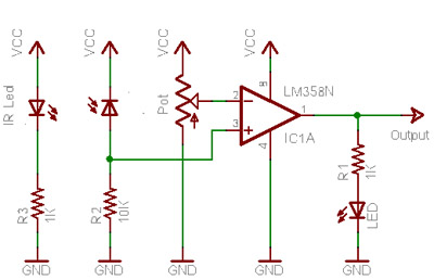
this can be achieved by comparing the output voltage with a reference voltage
for this operation a COMPARATOR is used.it is a special mode of operational amplifier.
here we will be using a LM358 ic as a comparator.it is an 8 pin ic consisting of two comparators.

a comparator consists of two input terminals. they are inverting terminal(-) and non-inverting terminal(+)
when the voltage at (+) is grater than that of(-)then output will be equal to the Vcc given to the ic
if voltage at(+) is less than (-) then the out put will be equal to 0V.
so the output from the sensor is connected to (+)pin and a potentiometer is connected to the(-)pin
so that the reference voltage can be varied
the over all sensor circuit will be

0V for black(logic zero)
5V for white(logic one)
an color led is used as indicator for the sensor
you can make two sensors using a single LM358 IC
to make a line-follower we will need two sensors
sensor arrangement will be as follows

so the overall logic will be
IF A SENSOR ON WHITE SURFACE THE CORRESPONDING
MOTOR GOES FORWARD
IF A SENSOR IS IN BLACK SURFACE THE CORRESPONDING
MOTOR WILL BE STOPPED
BUT how to achieve this??
here we are just switching the motor on and off so we need a SWITCH that is controlled by the signal from the sensor.
we know that switch we call it as"TRANSISTOR"
A transistor acts as a closed switch in saturation region and as a open switch in cutoff region
i'm using a BC547 transistor. the over all circuit will be
 the working model

the question is HOW THE ROBOT SEANCES THE LINE ?
or COLOR OF THE SURFACE
first let us discuss about the properties of a colored body.
if surface of a body is RED means that object is reflecting red color and absorbing all remaining colors.
if a body is white it means it is perfectly reflecting all colors.
if a body is black it means it is perfectly absorbing all colors.
white body is a perfect emitter and black body is a perfect absorb-er
not only visible colors.for almost all lights(but we practically use IR(infrared)

an IR sensor consists of an IR source and an IR detector
IR led is used as a source a PHOTO DIODE is used as a detector to respond to the reflected light
from the surface.

IR led
better not use more than 1Kohm

PHOTO DIODE
unlike an led a photo diode is operated in reverse biased condition.when it is in reversed biased condition
if there is no light falling on the diode it will exert a high impedance(resistance).if light falls on the diode resistance of the diode will decreased.(almost short circuit)
some times these are referred as simply RX(led-transmitter) and TX(photo diode--receiver).they
the basic sensor circuit will be as follows. don't forget to arrange arrange the led and diode side bi side.

so the photo diode acts as a short circuit so the voltage at the output will be almost equal to "0V"
in case of a black body or space(no object in front of sensor) then no light falls on the diode so it will act like a open circuit.so voltage at output will be almost equal to "5V"
the overall result will be
5V for black(logic one)
0V for white(logic zero)
if the 10K resistor and the photo diode positions in the above circuit are interchanged the logic will be reversed
0V for black(logic zero)
5V for white(logic one)
but this circuit has its own drawbacks. like it is sensitive to ambient light.some times the output voltage may not be an exact value.
for proper operation we need a sharp working sensor and adjustable sensitivity.
this can be achieved by comparing the output voltage with a reference voltage
for this operation a COMPARATOR is used.it is a special mode of operational amplifier.
here we will be using a LM358 ic as a comparator.it is an 8 pin ic consisting of two comparators.

a comparator consists of two input terminals. they are inverting terminal(-) and non-inverting terminal(+)
if voltage at(+) is less than (-) then the out put will be equal to 0V.
so the output from the sensor is connected to (+)pin and a potentiometer is connected to the(-)pin
so that the reference voltage can be varied
the over all sensor circuit will be
0V for black(logic zero)
5V for white(logic one)
an color led is used as indicator for the sensor
you can make two sensors using a single LM358 IC
to make a line-follower we will need two sensors
sensor arrangement will be as follows

IF A SENSOR ON WHITE SURFACE THE CORRESPONDING
MOTOR GOES FORWARD
IF A SENSOR IS IN BLACK SURFACE THE CORRESPONDING
MOTOR WILL BE STOPPED
BUT how to achieve this??
here we are just switching the motor on and off so we need a SWITCH that is controlled by the signal from the sensor.
we know that switch we call it as"TRANSISTOR"
A transistor acts as a closed switch in saturation region and as a open switch in cutoff region
i'm using a BC547 transistor. the over all circuit will be


10 comments:
what man vamsi evry thng is fine at the end wt that funny thing.......lol!
sir
i made that video long before currently im not having any editer so i posted as it is
"let it be a bit funny "
Plz provide us the coding for line following robot for 89s52
how robot steering it self?
thank you....its amazing
can you provide circuit diagram for this it will be help full
can you provide circuit diagram for this it will be help full
Plz plz plz plz plz Plz plz plz plz plz Plz plz plz plz plz Plz plz plz plz plz Plz plz plz plz plz Plz plz plz plz plz Plz plz plz plz plz Plz plz plz plz plz Plz plz plz plz plz Plz plz plz plz plz Plz plz plz plz
tell me the coding
tell me the programming code
my line follower was not going straight to the path it travel only left right .it has be move straight but it cant not .
Post a Comment