Friday, 28 June 2013

home made printed circuit board


I felt bored of using the universal PCB or the DOT board for my projects so i thought of making one printed circuit board after googling for couple of days i found the chemicals for this process
1)FeCl3
2)H2O(available in your everywhere for free)
3)H2O2(available in medical shops called hydrogen peroxide

before every thing first you have to make a schematic and board file of your circuit.
for that you require any CAD software for PCB designing.

i used Eagle software....its so cool..
first make schematic of the circuit of your interest and make its board file
save the board file as PDF and print it in black colour using a laser printer

NOTE: while printing do not forget to keep it in its original size. If you shrink the image you won't get a perfect PCB

take a print out and soak it in worm water.


take a PCB copper clad sheet of same size

place it in such a whay that copper side toches the print side of the paper and heat it with iron box

after that apply hydrogen peraxide on it and sloly rub the paper


 the paper melts and comes out of the PCB
 only the black laser printer ink stays on it

take a permanant CD marker and correct the missed paths on it
  
finally dip this board in to ferric chloride. actually it is available in the form of power . you have to mix it with water and make  the solution.
after that dip it completely in the solution and mix it slowly. the chemical is a kind of dangerous. so i made a mixing mechanism for that ..

take a look at the video:

after that you will need a PCB driller to make the holes for the components.it is a hand driller will cost around  Rs 100/- 

Making PCBs is fun but you must be careful with the chemicals 
Preferred to use hand gloves.

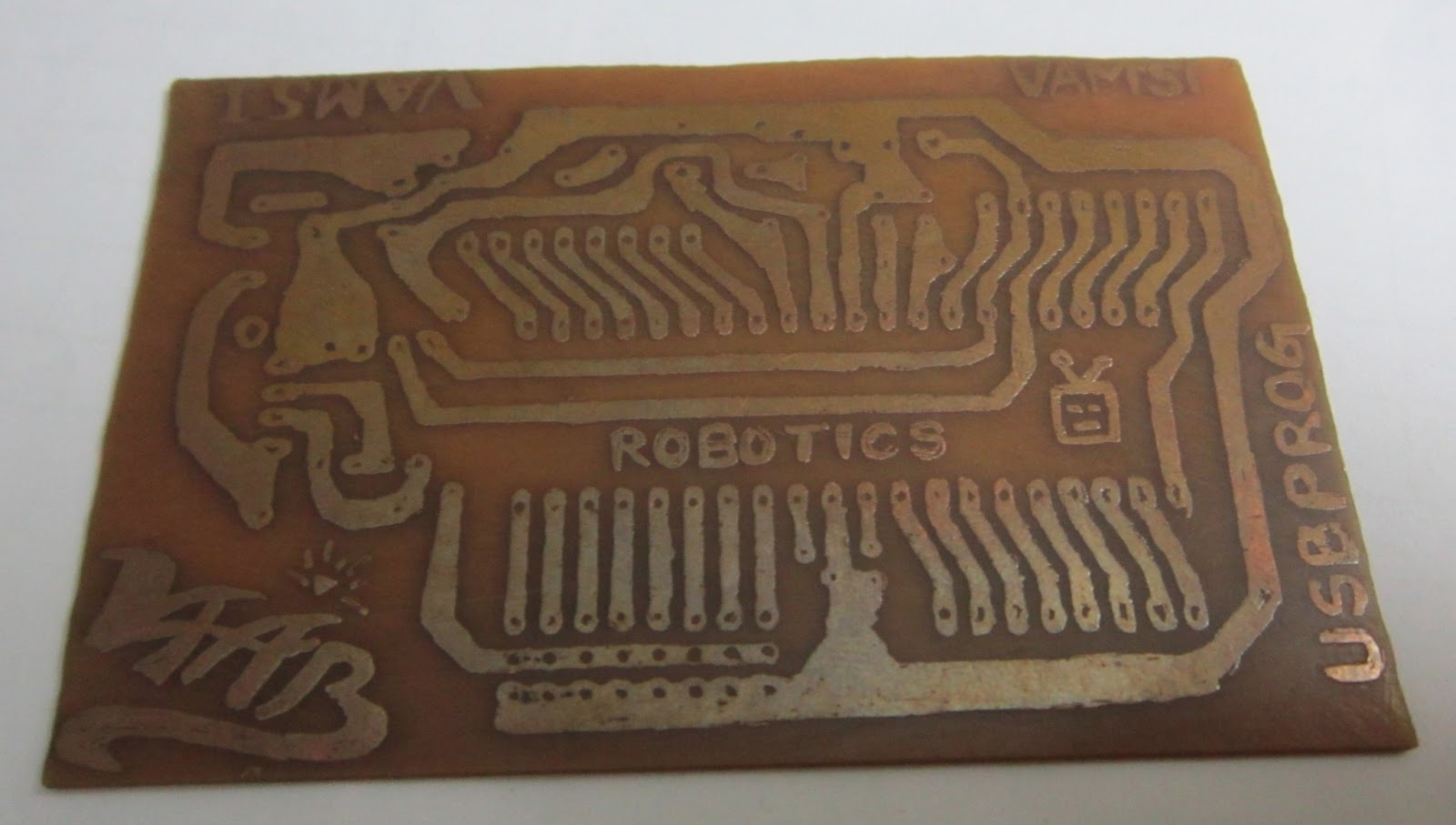
Enjoy.........you can write your names and logos on PCBs using a permanent marker.............
just like the first picture.

Saturday, 30 March 2013

USB programmable Propeller LED Display


Here is an ATmega8 based USB programmable POV Training kit.

This kit was designed for students those who are very much interested in working this POV concept. 
  • No need of any external programmer.
  • you can directly program this kit  from your PC/Laptop USB port.
  • Mechanically stable design.
  • Very easy to build.
  • Perfect delay calculations.


After a lot of handwork we finally came out with our best design.
Special Thanks
 to 
VARMA NAIDU sir
  For your technical and financial support.


 This video helps in assembling this kit 


Before programming the device first the USBasp drivers must be installed in the PC/Laptop. All the necessary soft wares and documents will be provided along with the KIT.
   PROGRAMMING PROCESS OF THE KIT


This is the basic block diagram of  PCB of POV kit on which you can observer the locations of and arrangement of  components.

FOR THOSE WHO WANT TO BUY THE KIT:

http://www.ebay.in/itm/USB-programmable-Rotating-LED-display-/291120480230?


FREE SHIPPING ALL OVER INDIA

MAIL US AT
vaabrobotics@gmail.com

Friday, 8 February 2013

Basic PC controlled robot

             A PC controlled robot is robotic platform that operates based on the data transmitted from the PC 
 serial COM port.

COM port is a 9 pin port that transmit data serially using UART(Universal asynchronous reception and transmission)  protocol. This is a full duplex which means one can transmit and receive data simultaneously.
Just like a USB port a PC will have a COM port at its back. It looks like this...


Though this port is having 9 pins we deal with only two pins. The are...
         PIN 2:Serial Receiver(Rx)
              PIN 3:Serial Transmitter(Tx) 
PIN 5:Signal Ground 
if your PC is not having a serial port you can use a USB to Serial cable..

The connections of of PC and microcontroller will be as follows

We connected the circuit....but ..
Can a microcontroller understand the data sent by a PC ?
Have you seen the word "TTL" in the above picture..........? 
it stands for (Transistor Transistor Logic). In which a logic '0' is represented by 0V
                                                                                logic '1' is represented by 5V
but the data transferred from the PC will follow RS-232(Recommended standard) logic
The RS-232 standard defines the voltage levels that correspond to logical one and logical zero levels for the data transmission and the control signal lines. Valid signals are either in the range of +3 to +15 volts or the range -3 to -15 volts; the range between -3 to +3 volts is not a valid RS-232 level. For data transmission lines (TxD, RxD and their secondary channel equivalents) logic one is defined as a negative voltage, the signal condition is called marking. Logic zero is positive and the signal condition is termed spacing.  

So to convert the voltage levels we need a level converter. MAX232 chip is used to do this job.

MAX232 connections with PC 

Basically PC will have a male port. so take a female port and make this circuit and connect to the PC and microcontroller.


   now your microcontroller will receive the proper data from PC
Here comes the Question what microcontroller to choose?

Here i'm considering 8051 microcontroller...for beginners


now after the connection..... the programming for 8051 using keil microvision 3

Connecting motors to the microcontroller using an L293D motor driver
i connected the RA(1234) pins to Port1 lower pins
P1.0=>PA0
P1.1=>PA1
P1.2=>PA2
P1.3=>PA3

 before going through the code reader must know about 8051 microcontroller.
if you press reset it says "HEY" on hyper terminal

Code:
#include<reg51.h>

void serial_init()     // Initialize Timer 1 for serial communication
{
TMOD=0x20;  //Timer1, mode 2, baud rate 9600 bps
TH1=0XFD; 
SCON=0x50;
TR1=1;
}

unsigned char  recieve()  //Function to receive serial data
{
   unsigned char value;
   while(RI==0);
   value=SBUF;
   RI=0;
    return value;
}

void transmit(unsigned char data)  // Funtion to transmit serial data
{

SBUF=data;
while(TI==0);
TI=0;
}

void main()
{serial_init();
transmit('H');transmit('E');transmit('Y');// display "HEY" on serial hyperterminal
unsigned char x; while(1) { x= recieve();
if(x==w)
P1=0x0a;// forword
else if(x==a)
P1=0x06;// left turn
else if(x==w)
P1=0x09;// right turn
else if(x==w)
P1=0x05;// back
else
P1=0x00//stop
}
}
to execute this project you will need to open hyper terminal which is not possible in Windows7  instead you can use the following softwear
DOWNLOAD:  udp://tracker.ccc.de:80/announce
   select your COM port and settings as shown in the picture...
and type the data....in the field....
it starts.....working enjoy...............................................................

Sunday, 3 February 2013

interfacing 4*4 matrix keypad to Microcontroller


What is matrix key pad?

  Ans:  A matrix key pad is a two dimensional arrangement of switches in row and columns. This arrangement follows an algorithm to get the status of the keys. Here comes the questions:
 How a switch works ?
A switch is nothing but two conductive terminals and an adjustable contact that connects the two terminals. So that one can adjust a the position of the switch manually to make circuit "OPENED"  or "CLOSED"

        This switch  is called a "Tact switch",which is generally used to make matrix keypads. it consists of four terminals but opposite pins are shorted internally.
                                          How to connect the switch to a microcontroller?       
Before that don't forget that a switch simply "closes" or "opens" a circuit. 
But a microcontroller is a digital device that only understands "ZERO(0V)" or "ONE(5V)".
so we need a circuit that indicate the status of a switch in turms of "0" or '1"....
here it goes.....     

working of the circuitry is left to the reader's assignment
if switch close=1 and switch open =0 then it is called active high logic
if switch close=0 and switch open =1 then it is called active low logic


  • Reader must Google about the concept of    "Pull-up" and "Pull-down" resistor
  • The resistor in the above circuit prevents the              circuitry from "short circuit of  Vcc and Gnd" when the switch is pressed.


Now we go for the matrix key pad arrangement. Take a look at the figure below. the keys are arranged in   four rows and four columns. 
So we got 4+4 pins to interface this matrix key pad to the microcontroller.
Now how to check weather a switch is pressed or not....

The basic algorithm for matrix key pad ....
  Let us assume the row pins and columns are connected an 8 pin port
     7       6      5      4      3      2      1     0 
  R1   R2     R3    R4    C1   C2   C3   C4 
  
  1. Configure all row pins of microcontroller as outputs and column pins as input .(7,6,5,4 are output and 3,2,1,0 are input.) 
  2. pull -up all column pins
  3. write '1's to row pins so all row pins are at high state. 
  4. make R1 pin 0 and remaining pins high
  5. scan each column pin (if any key is pressed in this row then that particular column pin will be zero)
  6. make R2 pin 0 and remaining pins high
  7. scan each column pin (if any key is pressed in this row then that particular column pin will be zero)
  8. make R3 pin 0 and remaining pins high
  9. scan each column pin (if any key is pressed in this row then that particular column pin will be zero)
  10. make R4 pin 0 and remaining pins high
  11. scan each column pin (if any key is pressed in this row then that particular column pin will be zero)   
This is basic algorithm. initialize a variable and return the corresponding value to the variable. This algorithm
will be same for all microcontroller. Some expert developers add some additional hardware to it and makes it more reliable.  


Thursday, 13 September 2012

Programmable Robotic Platform

Many of beginners of robotics field feel that working with robots.If you are looking for a kick start robot kit here is the solution. recently Robogenisis released ATmega8 based development board in the market. which is very much compact in size and of affordable cost. with the help of this kit we developed a mini robot kit that is compatible with even Windows7  64 bit.

No special programmer is required as the board is self programmable.

introducing the   V-2 Bot..............................................


you can just program the robot using USB cable
This robot was designed by considering students and hobbyists of beginners and medium. this development environment will help the user to reduce his//her efforts in making connections as all the peripherals are by default connected to the respective pins of the microcontroller. This circuit consumes less power so just two 9V batteries are required.here comes the BOT take a look at this
  

KIT CONTENT:

  1. ATmega8L development board.
  2. 16*2 alpha numeric LCD display
  3. Bread board for prototyping
  4. Power supply plugs
  5. Robot chases
  6. 100RPM DC geared motors
  7. 7cm plastic wheels with tires
  8. clamps and screws and screw driver
  9. USB cable
   
currently this kit is available in Hyderabad
for more details mail us at:

vaabrobotics@gmail.com

Thursday, 2 August 2012

HC-SR04 ultrasonic sensor interfacing with 8051 microcontroller


If you want to make your robot sense the objects in it's surroundings i suggest you to go for an ULTRASONIC sensor.Though the IR based sensors are cheep, their working range may vary due change in ambient light and won't give accurate range values.
In case of ULTRASONIC sensors they work based on the principle of  RADAR(RAdio Detection And Ranging). A RADAR transmits electromagnetic "pulse" towards the target and receives the "echo" reflected by the target.

Then the range of the target is determined by the "time lagging" between transmitted pulse and the received "echo". Generally microwave and ultrasonic frequencies are used in RADARS
Our HC-SR04 ultrasonic sensor works similar to the  RADAR mechanism but in a simplified manner. This sensor consists of four PINS

1.Vcc------------------connect to 5V dc
2.Trigger--------------pulse input that triggers the sensor
3.Echo----------------indicates the reception of echo from the target
4.Gnd-----------------ground final

working with sensor step by step

                                Take a look at the timing diagram of HC-SR04 sensor
 
      This diagram describes the basic algorithm in distance measuring using the sensor.

 
STEP1.                                                                                                                                       Make "Trig" pin of the sensor high for 10µs. This initiates a sensor cycle. 
STEP2.                                                                                                                                              8 x 40 kHz pulses will be sent from the  transmitting piezzo transducer of the sensor, after which time the "Echo" pin on the sensor will go from low to high.
STEP3.                                                                                                                                               The 40 kHz sound wave will bounce off the nearest object and return to the sensor.
STEP4.                                                                                                                                       When the sensor detects the reflected sound wave, the Echo pin will go low again.
STEP5.  
     The distance between the sensor and the detected object can be calculated based on the length of time the Echo pin is high.
STEP6.                                                                                                                                     
        If no object is detected, the Echo pin will stay high for 38ms and then go low. 

configuring the 8051 microcontroller:

To inter face the sensor to AT89S51 microcontroller we need two I/O pins. One of them is external interrupt pin(INT0 or INT1) for measuring the pulse width at the echo pin. and  any other pin say P3.5 for trigger.

STEP1.                 Connect the trigger pin of sensor to P3.5 of AT89S51
STEP2.                 Connect the echo pin of the sensor to INT0 (P3.2) of AT89S51
STEP3.                 Configure the TIMER0 of 8051 in 16 bit mode with “GATE” bit enabled. If the GATE pin is enabled and timer run control bit TR0 is set, the TIMER0 will be controlled by INT0 pin. When INT0 is high then the TIMER0 starts counting. Whenever INT0 goes low TIMER0 holds its count. So load the TMOD register with 00001010==0x0A; (better refer to any book of 8051).
STEP4.                 As the INT0 pin is input don’t forget to declare the pin input. Write “1” to the pin to make it input.

algorithm

==>Send a 10 micro second high pulse at trigger
                                          Initially P3.5=0;
                                        P3.5=1;
                                       Delay(10 micro second);
                                         P3.5=0;
      ==>   "WAIT" until the sensor transmits the eight 40KHz pulses and signal reflection.
                            initially the "ECHO"pin is low when the transmitter completes the pulse the pin goes high then our TIMER0 starts counting.when input at INT0 goes low timer holds count.   logic for waiting:
                                while(INT0==0);
                                while(INT0==1); 
but some times due to errors in the sensor functioning the 8051 microcontroller may go into an "INFINITE LOOP" 
for that there are two remedies
1)use watch dog timer(present on AT89S52 and other advanced versions)
2)generate a delay of 40 milliseconds after triggering the ultrasonic sensor.
the second option is preferred for beginners.

      ==>TIMER0 value = time taken by the signal to (go forward+come back)
It meas the signal traces the whole distance twice. 
so time taken by the signal to travel the distance = TIMER0 value/2 
ULTRASONIC  pulse travels with the speed of sound 340.29 m/s = 34029 cm/s
range of target= velocity *time ==> 34029 * TIMER0/2
                                                  ==>  17015 * TIMER0
At 12MHz TIMER0 gets incremented for 1microsecond.
        RANGE    =    17015 centimeters/seconds  *  TIMER0 micro seconds

                           =    17015 centimeters/seconds *  TIMER0 * (10^-6)  seconds                 
                                     as            (1micro second=10^-6 seconds)
                        
                           =    17015 centimeters/secondsTIMER0 * (10^-6)  seconds 
                         
                             
                           =    17015  TIMER0     centimeters 
                                        (1000000)   
                           
                           =       TIMER0_______     centimeters 
                                    1000000/ 17015 

                           =       TIMER0_   centimeters 
                                    58.771

                   RANGE of target  =  TIMER0_   centimeters 
                                                            59
  
By using the formula we can calculate the range  of the target easily.

circuit diagram 

  CODE

      #include<REGX51.h>
#include<intrins.h>// for using
_nop_() function
        sfr16 DPTR =0x82;// you can use DPTR as a single 16 bit register
sbit trig=P3^5;
void send_pulse(void) //to generate 10 microseconds delay
{
TH0=0x00;TL0=0x00;
 trig=1;
 _nop_();_nop_();_nop_();_nop_();_nop_();
 _nop_();_nop_();_nop_();_nop_();_nop_();
 trig=0;
   
}

unsigned char get_range(void)
{
 unsigned char range;
 send_pulse();
    while(!INT0);//         in sake of these lines you can generate a delay of 40 Milli seconds=40000 micro
    while (INT0);//        
seconds
        DPH=TH0;DPL=TL0;
 TH0=0xFF;TL0=0xFF;
 if(DPTR<35000)//actually you need to use 38000 but the sensor may not work at higher levels
  range=DPTR/59;
  else
  range=0; // indicates that there is no obstacle in front of the sensor
  return range;
}
void main()
{//main begin
  TMOD=0x09;//timer0 in 16 bit mode with gate enable
  TR0=1;//timer0 run enabled
  TH0=0x00;TL0=0x00;
  P3|=0x04;//setting pin P3.2 to make it INPUT
          unsigned int target_range=0;
 while(1)
 {
    target_range=get_range();
        //make your own function to display the range value.better to use LCD
 }
}// end of main