


If you want to make your robot sense the objects in it's surroundings i suggest you to go for an ULTRASONIC sensor.Though the IR based sensors are cheep, their working range may vary due change in ambient light and won't give accurate range values.
In case of ULTRASONIC sensors they work based on the principle of RADAR(RAdio Detection And Ranging). A RADAR transmits electromagnetic "pulse" towards the target and receives the "echo" reflected by the target.


Then the range of the target is determined by the "time lagging" between transmitted pulse and the received "echo". Generally microwave and ultrasonic frequencies are used in RADARS
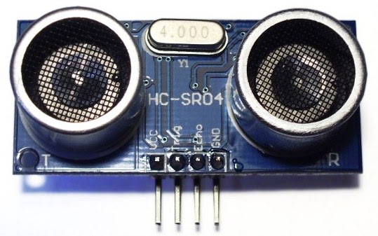
Our HC-SR04 ultrasonic sensor works similar to the RADAR mechanism but in a simplified manner. This sensor consists of four PINS
1.Vcc------------------connect to 5V dc
2.Trigger--------------pulse input that triggers the sensor
3.Echo----------------indicates the reception of echo from the target
4.Gnd-----------------ground final

working with sensor step by step
Take a look at the timing diagram of HC-SR04 sensor

This diagram describes the basic algorithm in distance measuring using the sensor.
initially the "ECHO"pin is low when the transmitter completes the pulse the pin goes high then our TIMER0 starts counting.when input at INT0 goes low timer holds count. logic for waiting:
while(INT0==0);
while(INT0==1);
but some times due to errors in the sensor functioning the 8051 microcontroller may go into an "INFINITE LOOP"
for that there are two remedies
1)use watch dog timer(present on AT89S52 and other advanced versions)
2)generate a delay of 40 milliseconds after triggering the ultrasonic sensor.
the second option is preferred for beginners.
==>TIMER0 value = time taken by the signal to (go forward+come back)
It meas the signal traces the whole distance twice.
so time taken by the signal to travel the distance = TIMER0 value/2
ULTRASONIC pulse travels with the speed of sound 340.29 m/s = 34029 cm/s
range of target= velocity *time ==> 34029 * TIMER0/2
==> 17015 * TIMER0
At 12MHz TIMER0 gets incremented for 1microsecond.
RANGE = 17015 centimeters/seconds * TIMER0 micro seconds
= 17015 centimeters/seconds * TIMER0 * (10^-6) seconds
as (1micro second=10^-6 seconds)
= 17015 centimeters/seconds * TIMER0 * (10^-6) seconds
= 17015 * TIMER0 centimeters
(1000000)
= TIMER0_______ centimeters
1000000/ 17015
= TIMER0_ centimeters
58.771
By using the formula we can calculate the range of the target easily.

STEP1.
Make
"Trig" pin of the sensor high for 10µs. This initiates a sensor cycle.
STEP2.
8 x 40 kHz pulses will be sent from
the transmitting piezzo transducer of the sensor, after which
time the "Echo" pin on the sensor will go from low to high.
STEP3.
The
40 kHz sound wave will bounce off the nearest object and return to the sensor.
STEP4.
When
the sensor detects the reflected sound wave, the Echo pin will go low again.
STEP5.
The distance between the sensor and the detected object can be calculated based on the length of time the Echo pin is high.
The distance between the sensor and the detected object can be calculated based on the length of time the Echo pin is high.
STEP6.
If no object is detected, the Echo pin will stay high for 38ms and then go low.
If no object is detected, the Echo pin will stay high for 38ms and then go low.
configuring the 8051 microcontroller:
To inter face the sensor to AT89S51 microcontroller we need two I/O pins. One of them is external interrupt pin(INT0 or INT1) for measuring the pulse width at the echo pin. and any other pin say P3.5 for trigger.
STEP1.
Connect the trigger pin of
sensor to P3.5 of AT89S51
STEP2.
Connect the echo pin of the
sensor to INT0 (P3.2) of AT89S51
STEP3.
Configure the TIMER0 of
8051 in 16 bit mode with “GATE” bit enabled. If the GATE pin is enabled and
timer run control bit TR0 is set, the TIMER0 will be controlled by INT0 pin.
When INT0 is high then the TIMER0 starts counting. Whenever INT0 goes low TIMER0
holds its count. So load the TMOD register with 00001010==0x0A; (better refer to
any book of 8051).
STEP4.
As the INT0 pin is input don’t
forget to declare the pin input. Write “1” to the pin to make it input.
algorithm
==>Send a 10 micro second high
pulse at trigger
Initially P3.5=0;
P3.5=1;
Delay(10 micro second);
P3.5=0;
==> "WAIT" until the sensor transmits the eight 40KHz pulses and signal reflection.initially the "ECHO"pin is low when the transmitter completes the pulse the pin goes high then our TIMER0 starts counting.when input at INT0 goes low timer holds count. logic for waiting:
while(INT0==0);
while(INT0==1);
but some times due to errors in the sensor functioning the 8051 microcontroller may go into an "INFINITE LOOP"
for that there are two remedies
1)use watch dog timer(present on AT89S52 and other advanced versions)
2)generate a delay of 40 milliseconds after triggering the ultrasonic sensor.
the second option is preferred for beginners.
==>TIMER0 value = time taken by the signal to (go forward+come back)
It meas the signal traces the whole distance twice.
so time taken by the signal to travel the distance = TIMER0 value/2
ULTRASONIC pulse travels with the speed of sound 340.29 m/s = 34029 cm/s
range of target= velocity *time ==> 34029 * TIMER0/2
==> 17015 * TIMER0
At 12MHz TIMER0 gets incremented for 1microsecond.
RANGE = 17015 centimeters/seconds * TIMER0 micro seconds
= 17015 centimeters/seconds * TIMER0 * (10^-6) seconds
as (1micro second=10^-6 seconds)
= 17015 centimeters/seconds * TIMER0 * (10^-6) seconds
= 17015 * TIMER0 centimeters
(1000000)
= TIMER0_______ centimeters
1000000/ 17015
= TIMER0_ centimeters
58.771
RANGE of target = TIMER0_ centimeters
59
By using the formula we can calculate the range of the target easily.
circuit diagram

CODE
#include<REGX51.h>
#include<intrins.h>// for using _nop_() function
sfr16 DPTR =0x82;// you can use DPTR as a single 16 bit register
sbit trig=P3^5;
void send_pulse(void) //to generate 10 microseconds delay
{
TH0=0x00;TL0=0x00;
trig=1;
_nop_();_nop_();_nop_();_nop_();_nop_();
_nop_();_nop_();_nop_();_nop_();_nop_();
trig=0;
}
unsigned char get_range(void)
{
unsigned char range;
send_pulse();
while(!INT0);// in sake of these lines you can generate a delay of 40 Milli seconds=40000 micro
while (INT0);// seconds
DPH=TH0;DPL=TL0;
TH0=0xFF;TL0=0xFF;
if(DPTR<35000)//actually you need to use 38000 but the sensor may not work at higher levels
range=DPTR/59;
else
range=0; // indicates that there is no obstacle in front of the sensor
return range;
}
void main()
{//main begin
TMOD=0x09;//timer0 in 16 bit mode with gate enable
TR0=1;//timer0 run enabled
TH0=0x00;TL0=0x00;
P3|=0x04;//setting pin P3.2 to make it INPUT
unsigned int target_range=0;
while(1)
{ target_range=get_range();
//make your own function to display the range value.better to use LCD
}
}// end of main
while(1)
{ target_range=get_range();
//make your own function to display the range value.better to use LCD
}
}// end of main

62 comments:
thank you so much for the information about ultrsonic sensor...
thanks a lot. its really useful. keep going...
it's working but the output is delayed... here are the problems that i'm facing:
1) Consistent change in distance.(If object is moved slowly and kept steady)
2) Delayed Reaction.
3) Hangs automatically.
-Could be due to:
i) Sudden or Fast changes.
ii) Moving closer to the module,i.e. reducing the distance
between module and object.
if you are using the same sensor HC-SR 04
some times the sensor may not get back to low(logic zero) after 38 Milliseconds. where your INTO pin will struck in
while(!INTO);
so it will struck.............
delayed response means....
how your are displaying the range
on LCD or 7 segment display
the delay may be caused by the functions of LCD...
Hello im working on ultrasonic sensor for obstacle detection, this means i dont need timer since i dont need to measure distance.
The problem is after the transmission of 8 pulses of 40khz the echo pin becomes low and my led is on (obstacle detected) even there is no obstacle around the sensor. I've generated a loop which checks for echo pin for 38ms then exits. This means led should be off if no obstacle detected, but its on
i am using the same sensor as yours with atmega32
HC-SR 04 is a distance measuring sensor
for obstacle detection you must use an other one
with three terminals which will give the direct logic voltage 0 or 1. it will be a three terminal device.
if you want to use the hc sr 04 with atmega32
you need to use input capture technique.
you need to use an other ultrasonic sensor for obstacle sensing. it will be a three terminal device which will give logic values according to the object presence (like zero and one)
the HC sr 04 will give you high when it detects an object and it stays high for some time. by calculating that time we determine the range.
Yes, i'm using the same sensor (HC-SR04).
The problem of the delay is not there anymore, i made changes in the LCD interfacing.
But it still gives wrong readings.It shows:
-1cm,when it is actually 13cm
-2cm,when it is actually 21cm
-3cm,when it is actually 33cm
-4cm,when it is actually 45cm and so on.
(I measured using a measuring tape)
And can this module be used to detect level of a liquid and volume of a container?
hello my name is rohit and i using this concept for my project but i want to convert the distance data into vibration the near the object the higher the vibrations please guide me in programming i am using this code to test the hardware with led display ORG 00H // origin
MOV DPTR,#LUT // moves the address of LUT to DPTR
MOV P1,#00000000B // sets P1 as output port
MOV P0,#00000000B // sets P0 as output port
CLR P3.0 // sets P3.0 as output for sending trigger
SETB P3.1 // sets P3.1 as input for receiving echo
MOV TMOD,#00100000B // sets timer1 as mode 2 auto reload timer
MAIN: MOV TL1,#207D // loads the initial value to start counting from
MOV TH1,#207D // loads the reload value
MOV A,#00000000B // clears accumulator
SETB P3.0 // starts the trigger pulse
ACALL DELAY1 // gives 10uS width for the trigger pulse
CLR P3.0 // ends the trigger pulse
HERE: JNB P3.1,HERE // loops here until echo is received
BACK: SETB TR1 // starts the timer1
HERE1: JNB TF1,HERE1 // loops here until timer overflows (ie;48 count)
CLR TR1 // stops the timer
CLR TF1 // clears timer flag 1
INC A // increments A for every timer1 overflow
JB P3.1,BACK // jumps to BACK if echo is still available
MOV R4,A // saves the value of A to R4
ACALL DLOOP // calls the display loop
SJMP MAIN // jumps to MAIN loop
DELAY1: MOV R6,#2D // 1uS delay
LABEL1: DJNZ R6,LABEL1
RET
DLOOP: MOV R5,#100D // loads R5 with 100D
BACK1: MOV A,R4 // loads the value in R4 to A
MOV B,#100D // loads B with 100D
DIV AB // isolates the first digit
SETB P1.0 // activates LED display unit D1
ACALL DISPLAY // calls DISPLAY subroutine
MOV P0,A // moves digit drive pattern for 1st digit to P0
ACALL DELAY // 1mS delay
ACALL DELAY
MOV A,B // moves the remainder of 1st division to A
MOV B,#10D // loads B with 10D
DIV AB // isolates the second digit
CLR P1.0 // deactivates LED display unit D1
SETB P1.1 // activates LED display unit D2
ACALL DISPLAY
MOV P0,A // moves digit drive pattern for 2nd digit to P0
ACALL DELAY
ACALL DELAY
MOV A,B // moves the remainder of 2nd division to A
CLR P1.1 // deactivates LED display unit D2
SETB P1.2 // activates LED display unit D3
ACALL DISPLAY
MOV P0,A // moves the digit drive pattern for 3rd digit to P0
ACALL DELAY
ACALL DELAY
CLR P1.2 // deactivates LED display unit D3
DJNZ R5,BACK1 // repeats the display loop 100 times
RET
DELAY: MOV R7,#250D // 1mS delay
LABEL2: DJNZ R7,LABEL2
RET
DISPLAY: MOVC A,@A+DPTR // gets the digit drive pattern for the content in A
CPL A // complements the digit drive pattern (see Note 1)
RET
LUT: DB 3FH // look up table (LUT) starts here
DB 06H
DB 5BH
DB 4FH
DB 66H
DB 6DH
DB 7DH
DB 07H
DB 7FH
DB 6FH
END
tell me if it is correct or not please reply on my mail id rohitpandey366@gmail.com thanks in advance
your program works fine but tell me how can i hook up the range detected by the program by timer and use this value to generate a pwm signal to run a dc motor of 6 volt but i want to operate it in a manner such as the maximum range gives no or low rpm and as distance reduces from the obstacle the rpm get increased can you please give a program for such problem
please help me in programming the data received to genrate pwm signal to run a dc motor with max range no rpm and min range max rpm thank you
Sorry for all the trouble.
It's workin very smoothly, had put too many delays.
Thanks a lot for the code, it's running beautifully.
how can i display the distance measured on the 7-segment display....
please help.
plz can sum1 mail the entire c code with lcd interfacing to ammu2991@yahoo.in...its urgent
first get some knowledge of LCD or 7 segment and then interface the sensor.....
please do not ask for the complete code
first give it a try.....
hey thanks ur code helped alot but plz can u further explain this condition
if(DPTR<35000)
some times the sensor echo pin may not return back to zero level
so even after 38ms
it means if your timer gives more than that
your sensor is not working
so i calibrated my sensor it gave me around
35000 microseconds width at "no object"
so to omit that condition and get perfect range i used that condition
#include
#include
#define port P2
#define dataport P0
sfr16 DPTR =0x82;
sbit trig=P3^5;
sbit rs=port^0;
sbit rw=port^1;
sbit e=port^2;
void delay(unsigned int msec)
{
int i,j;
for(i=0;i<msec;i++)
for(j=0;j<1275;j++);
}
void lcd_cmd(unsigned char item)
{
dataport = item;
rs= 0;
rw=0;
e=1;
delay(1);
e=0;
return;
}
void lcd_data(unsigned char item)
{
dataport = item;
rs= 1;
rw=0;
e=1;
delay(1);
e=0;
return;
}
void lcd_data_string(unsigned char *str)
{
int i=0;
while(str[i]!='\0')
{
lcd_data(str[i]);
i++;
delay(1);
}
return;
}
void send_pulse(void)
{
TH0=0x00;TL0=0x00;
trig=1;
_nop_();_nop_();_nop_();_nop_();_nop_();
_nop_();_nop_();_nop_();_nop_();_nop_();
trig=0;
}
unsigned int get_range(void)
{
int range=0;
int s;
send_pulse();
delay(40);
DPH=TH0;DPL=TL0;
TH0=0xFF;TL0=0xFF;
lcd_cmd(0x81);
delay(2);
lcd_data_string("output:");
lcd_cmd(0x8a);
if(DPTR<35000)
{
range=DPTR/59;
s=range/100;
range=range%100;
if(s!=0)
{
lcd_data(s+48);
}
else
{
lcd_cmd(0x06);
s=range/10;
range=range%10;
lcd_data(s+48);
lcd_data(range+48);
lcd_data(' ');
}
}
else
{
range=0;
lcd_cmd(0x06);
lcd_data(0);
}
return range;
}
void main()
{
lcd_cmd(0x38);
lcd_cmd(0x0c);
delay(2);
lcd_cmd(0x01);
delay(2);
lcd_cmd(0x81);
delay(2);
lcd_data_string("start");
delay(20);
TMOD=0x09;
TR0=1;
TH0=0x00;TL0=0x00;
P3=0x04;
while(1)
{ get_range();
delay(2);
}
}
output always shows 45
cant locate the error....
guide plz
Hi Vamsi Danda Sir, my name is Himanshu Vasani.I want to interface ultra sonic module and display distance on LCD module.What changes should I make in the above program for the same?
hey
the code is working fine in proteus simulation but in the hardware its is not displaying anything on lcd
i even pulled up P0 by 10k resistors
any guidance plz
or should i change compiler
how do u confirm that HEX transferred to 8051 is correct
what about the crystal frequency you are using?
exactly which version of 8051 you are using?
check the Vcc supply
less voltage may cause brown out reset
i am using 12MHz crystal
atmel 89c51
Vcc = 4.75 V
what misght be the possbile reasons for this
hello
it had been really helpful
but i am still stuck
at i cant find the triggering pulse
it shows in proteus simulation but not in hardware connected to CRO
Thanks for the code! I was implemented distance measure application by using Infrared sensor. But here i want to sample the IR signal, so that we can measure the distance very accuratly. So my question is Home many samples i have to take to sample the ir signal
Hello Sir,
nice information abt line follower robot.
We r working under same project in our college we have used Atmega8L microcontroller, L293D motor controller(we purchase robot online),WinAvr(4 ver),flash boot software for interface on computer system & connected them via cable.But we r facing one problem is that we are unable to reset it to normal mode the robot continuously following same program that loaded last time .How to solve this problem?
Please help us sir .......
so your using boot flash to program your device
there r two modes of operations (program mode and execution mode)
so you have to find the boot reset pin
if you connect the pin to ground and push the reset button then your device will be recognized by the PC
then try program it.
after loading program
disable boot reset pin (disconnect from ground)
and push the reset button
then your code will start execution...
better mail me at vaabrobotics@gmail.com
for further clarifications
sir its really good...pls explain me how its calculating distance.
its a silly question?
check the formula in the yellow block
all ready discussed in the article
please...........
go through the article before you post your question....
Hello sir...is it true that v should not use SCR04 for obstacle detection application?
no you can use it for obstacle detection.
but you have to trigger the sensor every time when you are checking for obstacle
so little more coding is required.
while(!INT0); //in sake of these lines you can generate a delay of 40 Milli seconds=40000 micro
while (INT0);
DPH=TH0;DPL=TL0;
TH0=0xFF;TL0=0xFF;
what is the meaning of this code
can we interface voice chip APR9600 to this circuit? if yes then plz send me the circiut dia....
hi karun
generating exact time delay on 8051 at 12mhz will be lil difficult so i used that while
as the CPU runs at(1/12 of clock called the machine cycle = 1us) and delay will give you some random garbage range value if your sensor is not working as you are NOT checking for echo pin
actually im using the data-pointer(16 bit) register the DPTR to calculate the time
if you check the "regx51.h" you wont find DPTR as single( but DPL,DPH are avilable)
so i used the "sfr16" macro to make a DPTR rigister...(just a carzy try)
hey actually it worked...
hi vedika
first why you want to interface the voice play back device to this.circuit?
if the apr9600 is already loaded some voice
you can interface .
Sir, can I use your code on 3 pins ultrasonic sensor?
there are 2 types of 3 pin sensor
1)ping sensor =both trigger and echo are interconnected
2)digital sensor=this will only sense the presence of an object like digital out put 0 or 1
you can use it as normal i/o sensor you cant get range...
we have to write any other program for lcd interfacing or the above is ok for the display of distance
if you can help than please reply me on my email id that is : animesh5522@gmail.com
No you have to write code for LCD interfacing separately...
check the above comments some one added code for for LCD interfacing also
Sir see in program, trig is declared P3^1 but saying to connect P3^5. i'm confused, and also why this P1=0xff; and P3|=0x04; ??? is it compulsory ??
thanks man for identifying that mistake i made the changes check once again.
no need of P1=0xff;
but P3=0x04; is important
when you are using a pin of 8051 as input the last bit written to this pin must be '1' as P3^2 is INT0 the echo pin .
how can i generate o/p using buzzzer instead of led where buzzer frequency depends on the range usin c code
#include
#include
#define port P2
#define dataport P0
sfr16 DPTR =0x82;
sbit trig=P3^5;
sbit rs=port^0;
sbit rw=port^1;
sbit e=port^2;
void delay(unsigned int msec)
{
int i,j;
for(i=0;i<msec;i++)
for(j=0;j<1275;j++);
}
void lcd_cmd(unsigned char item)
{
dataport = item;
rs= 0;
rw=0;
e=1;
delay(1);
e=0;
return;
}
void lcd_data(unsigned char item)
{
dataport = item;
rs= 1;
rw=0;
e=1;
delay(1);
e=0;
return;
}
void lcd_data_string(unsigned char *str)
{
int i=0;
while(str[i]!='\0')
{
lcd_data(str[i]);
i++;
delay(1);
}
return;
}
void send_pulse(void)
{
TH0=0x00;TL0=0x00;
trig=1;
_nop_();_nop_();_nop_();_nop_();_nop_();
_nop_();_nop_();_nop_();_nop_();_nop_();
trig=0;
}
unsigned int get_range(void)
{
int range=0;
int s;
send_pulse();
delay(40);
while(!INT0);
while(INT0); //Is it use for checking continuosly echo==1, after that timer stop and value in DPTR remains.....????
DPH=TH0;DPL=TL0;
TH0=0xFF;TL0=0xFF;
lcd_cmd(0x81);
delay(2);
lcd_data_string("output:");
lcd_cmd(0x8a);
if(DPTR<35000)
{
range=DPTR/59;
s=range/100;
range=range%100;
if(s!=0)
{
lcd_data(s+48); // should there be lcd_data(range+48) and lcd_data(' ') also.......?????
}
else
{
lcd_cmd(0x06);
s=range/10;
range=range%10;
lcd_data(s+48);
lcd_data(range+48);
lcd_data(' ');
}
}
else
{
range=0;
lcd_cmd(0x06);
lcd_data(0);
}
return range;
}
void main()
{
lcd_cmd(0x38);
lcd_cmd(0x0c);
delay(2);
lcd_cmd(0x01);
delay(2);
lcd_cmd(0x81);
delay(2);
lcd_data_string("start");
delay(20);
TMOD=0x09;
TR0=1;
TH0=0x00;TL0=0x00;
P3=0x04;
while(1)
{ get_range();
delay(2);
}
}
I m using AT89S52 uc with oscillator freq 11.0592Mhz.
Problem: it continuosly desplays 44 on LCD
Please help....
hi sir...i want to make an led to light up when the sensor detects any obstacle...
//////
void main()
{//main begin
unsigned int target_range = 0;
TMOD = 0x09 ;//timer0 in 16 bit mode with gate enable
TR0 = 1 ;//timer0 run enabled
TH0 = 0x00 ;
TL0 = 0x00 ;
P3 = 0x04 ;//setting pin P3.2 to make it INPUT
while(1)
{
target_range = get_range();
if(P3_2 = 0) //if the echo pin goes low
{
P1_0 = 0; //the led (port 1.0) lights up
}
else
{
P1_0 = 1; //else its not
}
}
}// end of main
and when i compile it..it says that the code is unreachable at P1_0
pls help me :)
if(P3_2 = 0) //if the echo pin goes low
in this statement you have to write '==' instead of '='
'=' is assignment operator
'==' is a relational operator
P1_3=0; will store '0' in P1_3
usage of this inside "if" has no effect..
if(P1_3==0) is wright statement
thanks a lot sir..the hex file has been generated but why is the led keep on luminous?i cant find the error.. does the statement right(the port setting syntax)?
//
{
P1_0 = 0; //the led (port 1.0) lights up
}
else
{
P1_0 = 1; //else its not
}
//
sensor gives active high on obstacle detection. that to be not more than 38 milliseconds.
so check of 1 on that pin instead of 0. and in side the if condition
{ led on;
delay of 1second ; if delay not used you cant see if the LED is on
led off;
}
the problem is still the same and i have no idea where is the mistake...here's my full program..
//////
#include
sfr16 DPTR=0x82;
void delay(unsigned int msec)
{
int i,j;
for(i=0;i<msec;i++)
for(j=0;j<1275;j++);
}
void send_pulse(void)
{
TH0=0x00;
TL0=0x00;
P3_5=1;
delay(10);
P3_5=0;
delay(10);
P3_5=1;
}
unsigned int get_range()
{
unsigned int range;
{
P3_5=1; //calibration
delay(300);
}
while(1)
send_pulse();
{
while(!INT0);
while(INT0);
DPH = TH0;
DPL = TL0;
TH0 = 0xFF;
TL0 = 0xFF;
if(DPTR<10000)
range=DPTR/59;
else
range=0;
return range;
}
}
void main()
{
unsigned int target_range = 0;
TMOD=0x09;
TR0=1;
TH0=0x00;
TL0=0x00;
P3_2=1;
while(1)
{
target_range=get_range();
if(P3_2==0)
{
P1_0=0;
delay(100);
}
else
{
P1_0=1;
delay(100);
}
}
}
//////
the echo pin seems receiving the signal from the transmitter...but the led just keep on lighting up...
is it because i put more than one "while(1)" loop?
// pin configuration : Echo : 3^2
// Trig : 1^7
// 7 seg: P2
// Com: 0^2 0^1 0^0
// MSB LSB
#include
sfr16 DPTR=0x82; //use DPTR as 16 bit reg51
unsigned int a,d1,d2,d3;
sbit m1=P3^2;
sbit trig=P1^7;
unsigned int range;
void transmit();
unsigned int receive();
void display1(unsigned int d1);
void display2(unsigned int d2);
void display3(unsigned int d3);
void msdelay(unsigned int );
int i;
unsigned int j,k,n;
void main()
{
P1=0x00; //make p1 as output
P2=0X00;
P0=0x00;
P3=0xff;
TMOD=0x19; // set timer 0 and timer 1 in mode 1 and set the gate for timer 0
transmit(); //function for transmit the ul.so.
receive(); //function for receiveng the ul.so.
d1=range/100; //calculation for the display the digit 1 on first 7 segment
a=range%100;
d2=a/10; //calculation for the display the digit 2 on second 7 segment
d3=a%10; //calculation for the display the digit 3 on third 7 segment
for(j=0;j<100;j++)
{
display1(d1); //display the digit 1 on first 7 segment
msdelay(1);
display2(d2); //display the digit 2 on second 7 segment
msdelay(1);
display3(d3); //calculation for the display the digit 3 on third 7 segment
msdelay(1);
}
}
void transmit(void) //function for transmit the ul.so.
{
TH1=0xff; //load TH0 with ff and load TL0 with f5 for 10 micro second delay
TL1=0xf5;
trig=1; //make high the trig pin
TR1=1; //run the clock
while(TF1==1) // wait for the 10 micro second
trig=0; //make triger low after 10 micro second
TR1=0;
TF1=0;
}
unsigned int receive()
{
TH0=0x00;
TL0=0x00;
TR0=1;
while(m1==0); //wait till the ul.so. complete the transmit the 8 pulses and get high and high m1 will turn on the timer
while(m1==1); //wait till the reflection receive is completed and low m1 will turn on the timer
DPH=TH0; //take timer value for distance calculation
DPL=TL0;
if(DPTR<35000) //if reflection is not received in 35000 micro so there is no obstacle within 400 cm
{
range=DPTR/59; //take the value of distance
TR0=0;
TF0=0;
}
else
{
range=0; //no obstacle
}
return(range);
}
void display1(unsigned int d1) //display function for first digit and first seven segment
{
P0=0xFB; //select display 1 MSB
switch(d1)
{
case 0: //display 0
P2=0xC0;
break;
case 1: //display 1
P2=0xF9;
break;
case 2: //display 2
P2=0xA4;
break;
case 3: //display 3
P2=0xB0;
break;
case 4: //display 4
P2=0x99;
break;
case 5: //display 5
P2=0x92;
break;
case 6: //display 6
P2=0x82;
break;
case 7: //display 7
P2=0xF8;
break;
case 8: //display 8
P2=0x80;
break;
case 9: //display 9
P2=0x90;
break;
default:
P2=0xBF;
break;
}
}
void display2(unsigned int d2) //display function for second digit and second seven segment
{
P0=0xFD; //select diplay2
switch(d2)
{
case 0:
P2=0xC0;
break;
case 1: //display 1
P2=0xF9;
break;
case 2: //display 2
P2=0xA4;
break;
case 3: //display 3
P2=0xB0;
break;
case 4: //display 4
P2=0x99;
break;
case 5: //display 5
P2=0x92;
break;
case 6: //display 6
P2=0x82;
break;
case 7: //display 7
P2=0xF8;
break;
case 8: //display 8
P2=0x80;
break;
case 9: //display 9
P2=0x90;
break;
default:
P2=0xBF;
break;
}
}
void display3(unsigned int d3) //display function for third digit and third seven segment
{
P0=0xFE; //select display 3 LSB
switch(d3)
{
case 0:
P2=0xC0;
break;
case 1: //display 1
P2=0xF9;
break;
case 2: //display 2
P2=0xA4;
break;
case 3: //display 3
P2=0xB0;
break;
case 4: //display 4
P2=0x99;
break;
case 5: //display 5
P2=0x92;
break;
case 6: //display 6
P2=0x82;
break;
case 7: //display 7
P2=0xF8;
break;
case 8: //display 8
P2=0x80;
break;
case 9: //display 9
P2=0x90;
break;
default:
P2=0xBF;
break;
}
}
void msdelay(unsigned int value)
{
unsigned int x,y;
for(x=0;x<value;x++)
for(y=0;y<1275;y++);
}
Its working fine. But when It goes above range it shows full 7segmnt(8.8.8.)
And than I have to push RESET for new measurement. Even I add default case, its not working.
So what correction I needed?
and how to use LCD 16x2 instead of 7segment.
good work
can u plzz give the code og gh311 interfacing with 8051
hey sir im sahil mohite i am doing automatic brake system project,i had write the program in asm in 89c51 micro controller ,i had program the ckt its works but i want to start and stop motor if the distance is less than 350mm .so how can i calculate the distance of object from the sensor.
ORG 00H // origin
MOV DPTR,#LUT // moves the address of LUT to DPTR
MOV P1,#00000000B // sets P1 as output port
MOV P0,#00000000B // sets P0 as output port
CLR P3.0 // sets P3.0 as output for sending trigger
SETB P3.1 // sets P3.1 as input for receiving echo
MOV TMOD,#00100000B // sets timer1 as mode 2 auto reload timer
MAIN: MOV TL1,#207D // loads the initial value to start counting from
MOV TH1,#207D // loads the reload value
MOV A,#00000000B // clears accumulator
SETB P3.0 // starts the trigger pulse
ACALL DELAY1 // gives 10uS width for the trigger pulse
CLR P3.0 // ends the trigger pulse
HERE: JNB P3.1,HERE // loops here until echo is received
BACK: SETB TR1 // starts the timer1
HERE1: JNB TF1,HERE1 // loops here until timer overflows (ie;48 count)
CLR TR1 // stops the timer
CLR TF1 // clears timer flag 1
INC A // increments A for every timer1 overflow
JB P3.1,BACK // jumps to BACK if echo is still available
MOV R4,A // saves the value of A to R4
ACALL DLOOP // calls the display loop
SJMP MAIN // jumps to MAIN loop
DELAY1: MOV R6,#2D // 1uS delay
LABEL1: DJNZ R6,LABEL1
RET
DLOOP: MOV R5,#100D // loads R5 with 100D
BACK1: MOV A,R4 // loads the value in R4 to A
MOV B,#100D // loads B with 100D
DIV AB // isolates the first digit
SETB P1.0 // activates LED display unit D1
ACALL DISPLAY // calls DISPLAY subroutine
MOV P0,A // moves digit drive pattern for 1st digit to P0
ACALL DELAY // 1mS delay
ACALL DELAY
MOV A,B // moves the remainder of 1st division to A
MOV B,#10D // loads B with 10D
DIV AB // isolates the second digit
CLR P1.0 // deactivates LED display unit D1
SETB P1.1 // activates LED display unit D2
ACALL DISPLAY
MOV P0,A // moves digit drive pattern for 2nd digit to P0
ACALL DELAY
ACALL DELAY
MOV A,B // moves the remainder of 2nd division to A
CLR P1.1 // deactivates LED display unit D2
SETB P1.2 // activates LED display unit D3
ACALL DISPLAY
MOV P0,A // moves the digit drive pattern for 3rd digit to P0
ACALL DELAY
ACALL DELAY
CLR P1.2 // deactivates LED display unit D3
DJNZ R5,BACK1 // repeats the display loop 100 times
RET
DELAY: MOV R7,#250D // 1mS delay
LABEL2: DJNZ R7,LABEL2
RET
DISPLAY: MOVC A,@A+DPTR // gets the digit drive pattern for the content in A
CPL A // complements the digit drive pattern (see Note 1)
RET
LUT: DB 3FH // look up table (LUT) starts here
DB 06H
DB 5BH
DB 4FH
DB 66H
DB 6DH
DB 7DH
DB 07H
DB 7FH
DB 6FH
END
plzz reply to it
i am getting some problem ....
just i want to take action upon particular distance from robo through pin 2.4and 2.5
......................................
this code gives distance accurately
but not gives any responce for pin 2.4and 2.5.....
pls sir help me as soon as possible ....
i will asways greatfull to u for this ...
thanks
#include
#include
#include
// for using _nop_() function
#define data_port P1
sfr16 DPTR=0x82;
sbit trig=P3^5;
sbit echo=P3^2;
sbit rs=P2^0;
sbit rw=P2^1;
sbit en=P2^2;
sbit m1=P2^3;
sbit m2=P2^4;
//sfr16 n=0x80;
void delay_ms(unsigned int msec)
{
int i,j;
for(i=0;i=100 && b<=400)
{
m1=1;
m2=1;
}
delay_ms(20);
if(b>=10 && b<=100)
{
m1=0;
m2=0;
}
delay_ms(20);
}
}
Email-pk8477053@gmail.com
DPH=TH0;DPL=TL0;
TH0=0xFF;TL0=0xFF;
in the above part whats the use of 2nd line (TH0=0xFF;TL0=0xFF;) in program? thanks in advances
sir is this possible to interface two ultrasonic sensors with p89v51rd2 microcontroller
Hola estoy haciendo un proyecto donde entre mas cerca este el sensor mas suena una bocina que quiero poner y entre mas lejos menos suena alguien me puede ayudar lo necesito en avr ensamblador
Thank you so much, your info was so useful
Post a Comment