Wednesday 16 October 2013

ARDUINO based Quadruped robot using 2 servos

I all ways wanted to make a quadruped robot. And finally got a chance to make one. So i wanted to simplify the design with least possible hardware.

working video


I checked in the market to get good servos and found these VS-2 servos. These servos provide up to
 3Kg-cm torque.

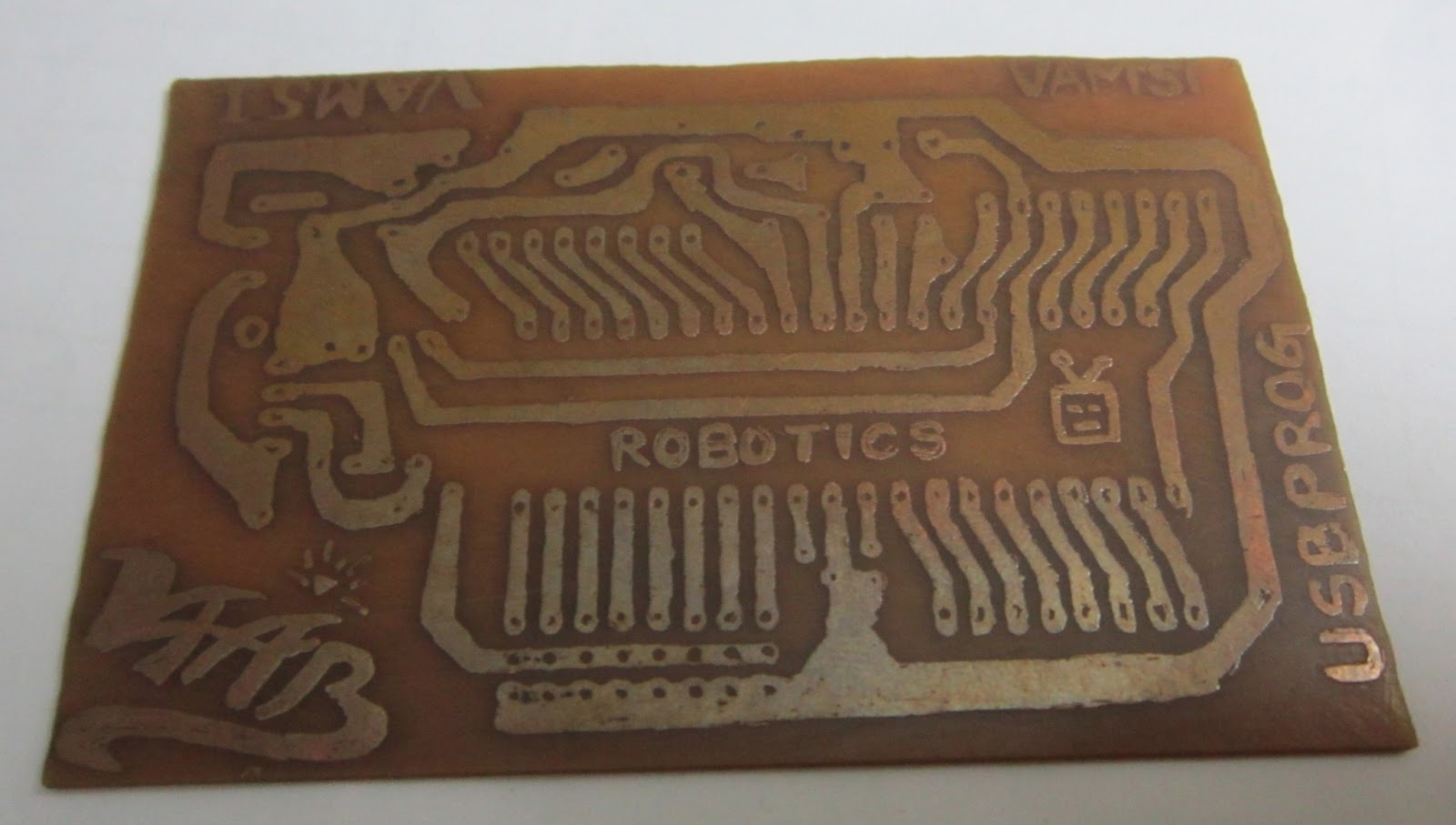
To control the servos i wanted to use ARDUINO. I got Arduino mega with me. But that board is little heavy and my robot cant bare it. So tried for arduino uno or nano. I'm not able to find one in the Indian market and the cost is going beyond the budget. So i thought of making my own Arduino. 


 This board consists of an ATmega8 microcontroller working at 16Mhz and almost all the pins are exposed in this board and each and every pin is associated with  supply and ground pins.

 To load the arduino sketch into this board i made a sketch loader for it. In traditional Arduino boards FTDT chips(FT232) are  used. It is a USB  to serial devise. I googled about and found a similar chip which is a little cheaper in my local market called CP2102 from silicon lcbs.


MECHANICAL ARRANGEMENT


CIRCUIT DIAGRAM:

In this circuit diagram i didn't showed the Power supply for Arduino. if you are using any standard Arduino you have to use a separate 9v supply for your Arduino board. In this project i used an ATmega8L microcontroller(operates from 3.3V to 5V) with Arduino boot-loader. So i used a common power supply for both Board and Motors.
NOTE: if you are using a common supply the circuit may get reset continuously due to more load of motors. To overcome this problem i used 2x1000uF capacitors accross Vcc and Gnd 

ARDUINO CODE :


#include <Servo.h>

Servo mot1;
Servo mot2;


void setup( )
{
  mot1.attach(9); // servo one to  digital pin 9 of arduino
  mot2.attach(10);// servo two to digital pin  10 of arduino

}
void loop( )
{
   mot1.write(60);
    mot2.write(120);

   delay(300);
 
   mot1.write(120);
    mot2.write(60);

   delay(300);


}


Sunday 13 October 2013

Analog 3-Axis Accelerometer interfacing with ATmega8 board

Every body is having a smart phone. The vary first game that you will look for is "TEMPLE RUN".
This game became favorite of many.

In the above situation how the player bends side?

I know what you will say "we tilt the smart phone left".

the question is how your mobile is able to sense the tilt. Here comes the concept of a small devise called

Accelerometer

 what is this thing?????????

It is a Micro Electro Mechanical device. For short MEMS.

How the accelerometer work?
when ever you tilt the accelerometer at any axis the module of the corresponding axis will sense the change in "g"(acceleration due to gravity) and produces a corresponding change in the terms of analog voltage. 

Now we are going to use an accelerometer to control the robot. This technique helps a physically challenged person to control the wheel chair with their hand gesture .
As shown in the above figure this sensor module is available at many models from different vendors. But the basic connection are same for all ADXL335 modules.

Actually this sensor module comes with an internal 3.3V voltage regulator. then you can directly use a 5V supply. otherwise you have to go for 3.3V supply. 

These X Y Z pins are the analog outputs from the sensor. As the device internally works at 3.3V the maximum voltage produced at these pins will be 3.3V

As we know that our microcontroller is digital and it cannot process the analog data directly. We need to convert the analog data into digital. An A/D converter is required for this process.

In this tutorial We are going to use an AVR microcontroller (ATmega8) based platform which is having an in built ADC mechanism in it.

This board was developed by ROBOGENESIS.
The specialty of the board is "NO EXTERNAL PROGRAMMER IS REQUIRED" .
It can be programmed through USB port.
comes along with a special library so any one can program the board.
Also compatible with ARDUINO programming.
For more info about This board mail us at : vaabrobotics@gmail.com
This board comes with a CD that include the necessary libraries for all the modules compatible with this microcontroller hardware.

So in this project we are going to use "adc.h" header file
which helps in using the ADC port of this board.

to check the ADC values at the respective levels we are going to interface an LCD too..
this will help us in calibrating the ADC data from the accelerometer.
to support the LCD port the "lcd.h" header file can be used.

connect the sensor X,Y,Z axis outputs to the ADC0, ADC1, ADC2 channels respectively

CODE FOR ATmega8 INTERFACING WITH ADXL335
#include<avr/io.h>                    //  I/O port definitions 
#define F_CPU 12000000UL  // frequency of the board
#include<util/delay.h>              // headder file for delay functions
#include"lcd.h"                        // LCD headder file
#include"adc.h"                       // ADC headder file
void main()
 lcd_init();   // initializing LCD
 adc_init();   // initializing ADC
 lcd_string("working"); // displays "working" on first row of LCD
 _delay_ms(1200);      // delay of 1.2seconds
 lcd_clear();               // LCD display cleared
lcd_cursor(0,0);         // setting cursor to row 0 column 0 position
 lcd_string("  X    Y    Z    "); // display on row 0
 unsigned char x,y,z; // variables
 while(1)
 {
  x=getdata(0x00);  //reading data from ADC0 storing in variable x
  y=getdata(0x01);  //reading data from ADC1 storing in variable y
  z=getdata(0x02);  //reading data from ADC2 storing in variable z
  
  lcd_cursor(1,0);  // setting cursor to row 1 colums 0 position
  lcd_num(x);       //displays the value of x
  lcd_cursor(1,5);  // setting cursor to row 1 colums 5 position
  lcd_num(y);        //displays the value of y
  lcd_cursor(1,10);// setting cursor to row 1 colums 10 position
  lcd_num(z);        //displays the value of z
 }
}

NOTE:ALL THE HEADER FILES ARE PROVIDED ALONG WITH THIS BOARD.....

Friday 28 June 2013

home made printed circuit board


I felt bored of using the universal PCB or the DOT board for my projects so i thought of making one printed circuit board after googling for couple of days i found the chemicals for this process
1)FeCl3
2)H2O(available in your everywhere for free)
3)H2O2(available in medical shops called hydrogen peroxide

before every thing first you have to make a schematic and board file of your circuit.
for that you require any CAD software for PCB designing.

i used Eagle software....its so cool..
first make schematic of the circuit of your interest and make its board file
save the board file as PDF and print it in black colour using a laser printer

NOTE: while printing do not forget to keep it in its original size. If you shrink the image you won't get a perfect PCB

take a print out and soak it in worm water.


take a PCB copper clad sheet of same size

place it in such a whay that copper side toches the print side of the paper and heat it with iron box

after that apply hydrogen peraxide on it and sloly rub the paper


 the paper melts and comes out of the PCB
 only the black laser printer ink stays on it

take a permanant CD marker and correct the missed paths on it
  
finally dip this board in to ferric chloride. actually it is available in the form of power . you have to mix it with water and make  the solution.
after that dip it completely in the solution and mix it slowly. the chemical is a kind of dangerous. so i made a mixing mechanism for that ..

take a look at the video:

after that you will need a PCB driller to make the holes for the components.it is a hand driller will cost around  Rs 100/- 

Making PCBs is fun but you must be careful with the chemicals 
Preferred to use hand gloves.

Enjoy.........you can write your names and logos on PCBs using a permanent marker.............
just like the first picture.

Saturday 30 March 2013

USB programmable Propeller LED Display


Here is an ATmega8 based USB programmable POV Training kit.

This kit was designed for students those who are very much interested in working this POV concept. 
  • No need of any external programmer.
  • you can directly program this kit  from your PC/Laptop USB port.
  • Mechanically stable design.
  • Very easy to build.
  • Perfect delay calculations.


After a lot of handwork we finally came out with our best design.
Special Thanks
 to 
VARMA NAIDU sir
  For your technical and financial support.


 This video helps in assembling this kit 


Before programming the device first the USBasp drivers must be installed in the PC/Laptop. All the necessary soft wares and documents will be provided along with the KIT.
   PROGRAMMING PROCESS OF THE KIT


This is the basic block diagram of  PCB of POV kit on which you can observer the locations of and arrangement of  components.

FOR THOSE WHO WANT TO BUY THE KIT:

http://www.ebay.in/itm/USB-programmable-Rotating-LED-display-/291120480230?


FREE SHIPPING ALL OVER INDIA

MAIL US AT
vaabrobotics@gmail.com

Friday 8 February 2013

Basic PC controlled robot

             A PC controlled robot is robotic platform that operates based on the data transmitted from the PC 
 serial COM port.

COM port is a 9 pin port that transmit data serially using UART(Universal asynchronous reception and transmission)  protocol. This is a full duplex which means one can transmit and receive data simultaneously.
Just like a USB port a PC will have a COM port at its back. It looks like this...


Though this port is having 9 pins we deal with only two pins. The are...
         PIN 2:Serial Receiver(Rx)
              PIN 3:Serial Transmitter(Tx) 
PIN 5:Signal Ground 
if your PC is not having a serial port you can use a USB to Serial cable..

The connections of of PC and microcontroller will be as follows

We connected the circuit....but ..
Can a microcontroller understand the data sent by a PC ?
Have you seen the word "TTL" in the above picture..........? 
it stands for (Transistor Transistor Logic). In which a logic '0' is represented by 0V
                                                                                logic '1' is represented by 5V
but the data transferred from the PC will follow RS-232(Recommended standard) logic
The RS-232 standard defines the voltage levels that correspond to logical one and logical zero levels for the data transmission and the control signal lines. Valid signals are either in the range of +3 to +15 volts or the range -3 to -15 volts; the range between -3 to +3 volts is not a valid RS-232 level. For data transmission lines (TxD, RxD and their secondary channel equivalents) logic one is defined as a negative voltage, the signal condition is called marking. Logic zero is positive and the signal condition is termed spacing.  

So to convert the voltage levels we need a level converter. MAX232 chip is used to do this job.

MAX232 connections with PC 

Basically PC will have a male port. so take a female port and make this circuit and connect to the PC and microcontroller.


   now your microcontroller will receive the proper data from PC
Here comes the Question what microcontroller to choose?

Here i'm considering 8051 microcontroller...for beginners


now after the connection..... the programming for 8051 using keil microvision 3

Connecting motors to the microcontroller using an L293D motor driver
i connected the RA(1234) pins to Port1 lower pins
P1.0=>PA0
P1.1=>PA1
P1.2=>PA2
P1.3=>PA3

 before going through the code reader must know about 8051 microcontroller.
if you press reset it says "HEY" on hyper terminal

Code:
#include<reg51.h>

void serial_init()     // Initialize Timer 1 for serial communication
{
TMOD=0x20;  //Timer1, mode 2, baud rate 9600 bps
TH1=0XFD; 
SCON=0x50;
TR1=1;
}

unsigned char  recieve()  //Function to receive serial data
{
   unsigned char value;
   while(RI==0);
   value=SBUF;
   RI=0;
    return value;
}

void transmit(unsigned char data)  // Funtion to transmit serial data
{

SBUF=data;
while(TI==0);
TI=0;
}

void main()
{serial_init();
transmit('H');transmit('E');transmit('Y');// display "HEY" on serial hyperterminal
unsigned char x; while(1) { x= recieve();
if(x==w)
P1=0x0a;// forword
else if(x==a)
P1=0x06;// left turn
else if(x==w)
P1=0x09;// right turn
else if(x==w)
P1=0x05;// back
else
P1=0x00//stop
}
}
to execute this project you will need to open hyper terminal which is not possible in Windows7  instead you can use the following softwear
DOWNLOAD:  udp://tracker.ccc.de:80/announce
   select your COM port and settings as shown in the picture...
and type the data....in the field....
it starts.....working enjoy...............................................................