


STEPPER MOTOR
Stepper motors, or steppers, are digitally controlled brushless motors that rotate a specific number of degrees (a step) every time a clock pulse is applied to a special translator circuit that is used to control the stepper. The number of degrees per step (resolution) for a given stepper motor can be as small as 0.72° per step or as large as 90° per step. Common general-purpose stepper resolutions are 15 and 30° per step.
Unlike RC servos, steppers can rotate a full 360° and can be made to rotate in a continuous manner like a dc motor (but with a lower maximum speed) with the help of proper digital control circuitry. Unlike dc motors, steppers provide a large amount of torque at low speeds, making them suitable in applications where low-speed and high-precision position control is needed. For example, they are used in printers to
control paper feed and are used to help a telescope track stars. Steppers are also
found in plotter- and sensor-positioning applications. The list goes on. To give you a
basic idea of how a stepper works, take a look at the Figure.

Here is a simple model depicting a 15° per step variable-reluctance stepper.The stationary section of the motor, called the stator, has eight poles that are spaced 45° apart. The moving section of the motor, called the rotor, is made from a ferromagnetic material (a material that is attracted to magnetic fields) that has six teeth spaced 60° apart.To make the rotor turn one step, current is applied, at the same time, through two opposing pole pairs, or coil pairs.The applied current causes the opposing pair
of poles to become magnetized. This in turn causes the rotor’s teeth to align with the poles, as shown in the figure.To make the rotor rotate 15° clockwise from this position, the current through coil pair 1 is removed and sent through coil pair 2.To make the rotor rotate another 15° clockwise from this position, the current is removed from coil pair 2 and sent through coil pair 3.The process continues in this way.To make the rotor spin counterclockwise, the coil-pair firing sequence is reversed.
TYPES OF STEPPER MOTORS
The model used in the last example was based on a variable-reluctance stepper. As it turns out, this model is incomplete—it does not show how a real variable-reluctance stepper is wired internally. Also, the model does not apply to a class of steppers referred to as permanent-magnet steppers. To make things more realistic, let’s take a look at some real-life steppers

This figure shows a physical model and schematic diagram of a 30° per step variable reluctance stepper. This stepper consists of a six-pole
(or three-coil pair) stator and a
four-toothed ferromagnetic rotor. Variable-reluctance steppers with higher angular resolutions are constructed with more coil pairs and/or more rotor teeth. Notice that
in both the physical model and the schematic, the ends of all the coil pairs are joined together at a common point. (This joining of the coil ends occurs internally within the
motor’s case.) The common and the coil pair free ends are brought out as wires from the motor’s case. These wires are referred to as the phase wires. The common wire is connected to the supply voltage, whereas the phase wires are grounded in sequence according to the table shown below.
UNI-POLAR STEPPER MOTOR
These steppers have a similar stator arrangement as the variable-reluctance steppers, but they use a permanent-magnet rotor and different internal wiring arrangements.Figure shows a 30° per step unipolar stepper. Its consists of a four-pole (or two coil pair) stator with center taps between coil pairs and a six-toothed permanent magnetic rotor. The center taps may be wired internally and brought out as one wire
or may be brought out separately as two wires. The center taps typically are wired to the positive supply voltage, whereas the two free ends of a coil pair are alternately grounded to reverse the direction of the field provided by that winding. As shown in the figure, when current flows from the center tap of winding 1 out terminal 1a, the top stator pole “goes north,” while the bottom stator pole “goes south.” This causes the rotor to snap into position. If the current through winding 1 is removed, sent through winding 2, and out terminal 2a, the horizontal poles will become energized, causing the rotor will turn 30°, or one step. In Fig , three firing sequences are shown. The first sequence provides full stepping action (what I just discussed). The second sequence, referred to as the power stepping sequence, provides full stepping
action with 1.4 times the torque but twice the power consumption. The third sequence provides half stepping (e.g., 15° instead of the rated 30°). Half stepping is made possible by energizing adjacent poles at the same time. This pulls the rotor in between the poles, thus resulting in one-half the stepping angle. As a final note,
unipolar steppers with higher angular resolutions are constructed with more rotor teeth. Also, uni polars come in either five- or six-wire types. The five-wire type has the center taps joined internally, while the six-wire type does not.


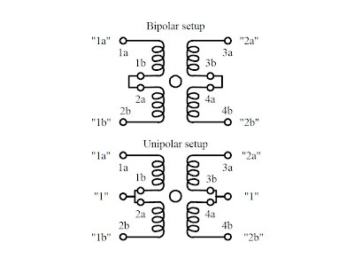
BIPOLAR STEPPER MOTOR
These steppers resemble unipolar steppers, but their coil pairs do not have center taps. This means that instead of simply supplying a fixed supply voltage to a lead, as was
the case in unipolar steppers (supply voltage was fixed to center taps), the supply voltage must be alternately applied to different coil ends. At the same time, the opposite end of a coil pair must be set to the opposite polarity (ground). For example, in
Figure, a 30° per step bipolar stepper is made to rotate by applying the polarities shown in the firing sequence table to the leads of the stepper. Notice that the firing sequence
uses the same basic drive pattern as the unipolar stepper, but the “0” and “1” signals are replaced with “+” and “−” symbols to show that the polarity matters. As you will see in the next section, the circuitry used to drive a bipolar stepper requires an
 H-bridge network for every coil pair. Bipolar steppers are more difficult to control than both uni polar steppers and variable-reluctance steppers, but their unique polarity-shifting feature gives them a better size-to-torque ratio. As a final note, bipolar
steppers with higher angular resolutions are constructed with more rotor teeth.
UNIVERSAL STEPPER MOTOR
 These steppers represent a type of unipolar-bipolar hybrid. A universal stepper comes with four independent windings and eight leads. By connecting the coil windings in parallel, as shown in Figure, the universal stepper can be converted into a
unipolar stepper. If the coil windings are connected in series, the stepper can be converted into a bipolar stepper.

"WHAT EVER THE TYPE OF STEPPER IS TO ROTATE IT THE BASIC LOGIC IS TO
CONNECT THE CENTER TAPS OF THE COILS TO POSITIVE TERMINAL OF SUPPLY
AND THE REMAINING ENDS OF COILS MUST BE GROUNDED(CONNECTED TO
NEGATIVE TERMINAL OF THE SUPPLY) IN THE ORDER DISCUSSED ABOVE"
for this "grounding" several techniques are used.but the main role of such devise will be"SWITCHING" the motor coils
the arrange ment will be


connect the in1,in2,in3,in4 pins of 2003 to the control logic
and follow the algorithm as per the type of motor

Stepper motors, or steppers, are digitally controlled brushless motors that rotate a specific number of degrees (a step) every time a clock pulse is applied to a special translator circuit that is used to control the stepper. The number of degrees per step (resolution) for a given stepper motor can be as small as 0.72° per step or as large as 90° per step. Common general-purpose stepper resolutions are 15 and 30° per step.
Unlike RC servos, steppers can rotate a full 360° and can be made to rotate in a continuous manner like a dc motor (but with a lower maximum speed) with the help of proper digital control circuitry. Unlike dc motors, steppers provide a large amount of torque at low speeds, making them suitable in applications where low-speed and high-precision position control is needed. For example, they are used in printers to
control paper feed and are used to help a telescope track stars. Steppers are also
found in plotter- and sensor-positioning applications. The list goes on. To give you a
basic idea of how a stepper works, take a look at the Figure.

Here is a simple model depicting a 15° per step variable-reluctance stepper.The stationary section of the motor, called the stator, has eight poles that are spaced 45° apart. The moving section of the motor, called the rotor, is made from a ferromagnetic material (a material that is attracted to magnetic fields) that has six teeth spaced 60° apart.To make the rotor turn one step, current is applied, at the same time, through two opposing pole pairs, or coil pairs.The applied current causes the opposing pair
of poles to become magnetized. This in turn causes the rotor’s teeth to align with the poles, as shown in the figure.To make the rotor rotate 15° clockwise from this position, the current through coil pair 1 is removed and sent through coil pair 2.To make the rotor rotate another 15° clockwise from this position, the current is removed from coil pair 2 and sent through coil pair 3.The process continues in this way.To make the rotor spin counterclockwise, the coil-pair firing sequence is reversed.
TYPES OF STEPPER MOTORS
The model used in the last example was based on a variable-reluctance stepper. As it turns out, this model is incomplete—it does not show how a real variable-reluctance stepper is wired internally. Also, the model does not apply to a class of steppers referred to as permanent-magnet steppers. To make things more realistic, let’s take a look at some real-life steppers

This figure shows a physical model and schematic diagram of a 30° per step variable reluctance stepper. This stepper consists of a six-pole
(or three-coil pair) stator and a
four-toothed ferromagnetic rotor. Variable-reluctance steppers with higher angular resolutions are constructed with more coil pairs and/or more rotor teeth. Notice that
in both the physical model and the schematic, the ends of all the coil pairs are joined together at a common point. (This joining of the coil ends occurs internally within the
motor’s case.) The common and the coil pair free ends are brought out as wires from the motor’s case. These wires are referred to as the phase wires. The common wire is connected to the supply voltage, whereas the phase wires are grounded in sequence according to the table shown below.
UNI-POLAR STEPPER MOTOR


These steppers have a similar stator arrangement as the variable-reluctance steppers, but they use a permanent-magnet rotor and different internal wiring arrangements.Figure shows a 30° per step unipolar stepper. Its consists of a four-pole (or two coil pair) stator with center taps between coil pairs and a six-toothed permanent magnetic rotor. The center taps may be wired internally and brought out as one wire
or may be brought out separately as two wires. The center taps typically are wired to the positive supply voltage, whereas the two free ends of a coil pair are alternately grounded to reverse the direction of the field provided by that winding. As shown in the figure, when current flows from the center tap of winding 1 out terminal 1a, the top stator pole “goes north,” while the bottom stator pole “goes south.” This causes the rotor to snap into position. If the current through winding 1 is removed, sent through winding 2, and out terminal 2a, the horizontal poles will become energized, causing the rotor will turn 30°, or one step. In Fig , three firing sequences are shown. The first sequence provides full stepping action (what I just discussed). The second sequence, referred to as the power stepping sequence, provides full stepping
action with 1.4 times the torque but twice the power consumption. The third sequence provides half stepping (e.g., 15° instead of the rated 30°). Half stepping is made possible by energizing adjacent poles at the same time. This pulls the rotor in between the poles, thus resulting in one-half the stepping angle. As a final note,
unipolar steppers with higher angular resolutions are constructed with more rotor teeth. Also, uni polars come in either five- or six-wire types. The five-wire type has the center taps joined internally, while the six-wire type does not.


BIPOLAR STEPPER MOTOR
These steppers resemble unipolar steppers, but their coil pairs do not have center taps. This means that instead of simply supplying a fixed supply voltage to a lead, as was
the case in unipolar steppers (supply voltage was fixed to center taps), the supply voltage must be alternately applied to different coil ends. At the same time, the opposite end of a coil pair must be set to the opposite polarity (ground). For example, in
Figure, a 30° per step bipolar stepper is made to rotate by applying the polarities shown in the firing sequence table to the leads of the stepper. Notice that the firing sequence
uses the same basic drive pattern as the unipolar stepper, but the “0” and “1” signals are replaced with “+” and “−” symbols to show that the polarity matters. As you will see in the next section, the circuitry used to drive a bipolar stepper requires an
 H-bridge network for every coil pair. Bipolar steppers are more difficult to control than both uni polar steppers and variable-reluctance steppers, but their unique polarity-shifting feature gives them a better size-to-torque ratio. As a final note, bipolar
steppers with higher angular resolutions are constructed with more rotor teeth.
UNIVERSAL STEPPER MOTOR
 These steppers represent a type of unipolar-bipolar hybrid. A universal stepper comes with four independent windings and eight leads. By connecting the coil windings in parallel, as shown in Figure, the universal stepper can be converted into a
unipolar stepper. If the coil windings are connected in series, the stepper can be converted into a bipolar stepper.


"WHAT EVER THE TYPE OF STEPPER IS TO ROTATE IT THE BASIC LOGIC IS TO
CONNECT THE CENTER TAPS OF THE COILS TO POSITIVE TERMINAL OF SUPPLY
AND THE REMAINING ENDS OF COILS MUST BE GROUNDED(CONNECTED TO
NEGATIVE TERMINAL OF THE SUPPLY) IN THE ORDER DISCUSSED ABOVE"
for this "grounding" several techniques are used.but the main role of such devise will be"SWITCHING" the motor coils
the arrange ment will be

but we need a devise to perform the switching operation for that i prefer the following ULN2003 it consists of 7 darlington array.refer the data sheet for more

the over all arrangement will be as follows

connect the in1,in2,in3,in4 pins of 2003 to the control logic
and follow the algorithm as per the type of motor


7 comments:
Hello,
Thank you for this tutorial, it's helping me understand steppers better. I have a situation where I have a fiber optic box that supplies light to a swimming pool. It was built in 1990 (ish) and parts are hard to find. There is an AC geared stepper motor inside that only has two wires. One wire goes right to a transformer the other to a relay. I spoke to the manufacturer but they don't make the motor any longer. I found a few online but they are between 250.00 and 300.00 for the motor (small 3.6 rpm motor that drives a color wheel). My question is, I found an identical motor with regard to specifications, but it's a 4 wire stepper. Is there a way to make that 4 wire motor work in a 2 wire implementation? Thank you in advance for any information you can supply, it's much appreciated.
-Jeff
i don't think that is a stepper motor. must be some low speed AC motor
check this link:
http://i00.i.aliimg.com/img/pb/936/742/512/512742936_724.jpg
That's what I thought, also. Here is what I got back from the manufacturer:
"The motor is a AC stepper motor with built in gear train. It was a specialty motor made by Haydon only. This particular one was made for a company called Fiberstar in Fremont California. I'm not sure if they are still in business."
This is the actual motor, but it does not say here "stepper". So possibly just an AC motor that's geared way down?
http://www.aqua-man.com/row_num.asp?Ic=40089
Thanks again,
jeff
So why don't you give it a try....get a normal homely AC switch (i mean the one in our switch boards it will be little safe to handle ) and a transformer as per motor requirement
. it will work. in India this type of motors are use in air cooler's swinging mechanism. i use the motor in the link i sent you.
Hi,
I’m really impressed with your blog article, such great & useful knowledge you mentioned here
Mattress Cleaning Singapore:-"Hooklights offer top flexible led car strip headlight, g5 and gm stepper motors in usa with reasonable price. Contact us - info@hooklights.com"
Visit Site :- http://www.hooklights.com/
i slso don't think that is a stepper motor. must be some low speed AC motor
check this link:
https://www.oyostepper.com/category-37-b0-Brushless-DC-Motor.html
BetMGM Casinos in PA & NJ Review - JTM Hub
BetMGM is the online 통영 출장안마 casino and sportsbook of 충청남도 출장마사지 MGM Resorts International. 진주 출장샵 The brand's most popular game is called "BETMGM Slots". It's a slot machine 1xbet korean with Rating: 4.1 · Review by Joe Kizlauskas 전라남도 출장마사지
Post a Comment