


Identifying the capacitor value is a bit difficult compared to that of resistor.At the beginning i felt a lot of trouble.
first let us discuss the working of a capacitor.
INSIDE THE CAPACITOR


first let us discuss the working of a capacitor.
INSIDE THE CAPACITOR
A simple capacitor consists of two parallel plates. When the two plates are connected to a dc voltage source (e.g., a battery), electrons are “pushed” onto one plate by the negative terminal of the battery, while electrons are “pulled” from the other plate by the positive terminal of the battery. If the charge difference between the two plates become excessively large, a spark may jump across the gap between them and discharge the capacitor. To increase the amount of charge that can be stored on the plates, a non-conducting dielectric material is placed between them. The dielectric acts as a “spark blocker” and consequently increases the charge capacity of the capacitor.Other factors that affect capacitance levels include the capacitor’s plate surface area and the distance between the parallel plates. Commercially, a capacitor’s dielectric may be either paper, plastic film, mica, glass, ceramic, or air, while the plates may be either aluminium disks, aluminium foil, or a thin film of metal applied to opposite sides of a solid dielectric. The conductor-dielectric-conductor sandwich may be left flat or rolled into a cylinder. The figure below shows some examples.


Here’s the best thing I could come up with in terms of a water analogy for a capacitor. Pretend that electrons are water molecules and that voltage is water pressure. The water capacitor is built from two balloons. Normally, the two balloons are filled with the same amount of water; the pressure within each one is the same (analogous to an uncharged capacitor). In the figure, a real capacitor is charged by a battery, whereas the water capacitor is “charged” using a pump or pressurized water source. The real capacitor has a voltage across its plates, whereas in the water capacitor there is a difference in pressure between the two balloons. When the real capacitor is removed from the battery, it retains its charge; there is no conductive path through which charges can escape. If the water capacitor is removed from the pressurized water source—you have to pretend that corks are placed in its lead pipes—it too retains its stored-up pressure. When an alternating voltage is applied across a real capacitor, it appears as if an alternating current (displacement current) flows through the capacitor due to the changing magnetic fields. In the water capacitor, if an alternating pressure is applied across its lead tubes, one balloon will fill with water and push against the other semi filled balloon, causing water to flow out it. As the frequency of the applied pressure increases, the water capacitor resembles a rubber membrane that fluctuates very rapidly back and forth, making it appears as if it is a short circuit (at least in ac terms). In reality, this analogy is overly simplistic and does not address the subtleties involved in a real capacitor’s operation. Take this analogy lightheartedly.
KINDS OF CAPACITORS
There are a number of different capacitor families available, each of which has defining characteristic features. Some families are good for storing large amounts of charge yet may have high leakage currents and bad tolerances. Other families may have great tolerances and low leakage currents but may not have the ability to store large amounts of charge. Some families are designed to handle high voltages yet may be bulky and expensive. Other families may not be able to handle high voltages but
may have good tolerances and good temperature performance. Some families may contain members that are polarized or nonpolarized in nature. Polarized capacitors, unlike nonpolarized capacitors, are specifically designed for use with dc fluctuating voltages (a nonpolarized capacitor can handle both dc and ac voltages). A polarized capacitor has a positive lead that must be placed at a higher potential in a circuit and has a negative lead that must be placed at a lower potential. Placing a polarized capacitor in the wrong direction may destroy it. (Polarized capacitors’ limitation to
use in dc fluctuating circuits is counterbalanced by extremely large capacitances.) Capacitors also come in fixed or variable forms. Variable capacitors have a knob that can be rotated to adjust the capacitance level. The symbols for fixed, polarized, and variable capacitors are shown below

CAPACITOR PACKAGES

These capacitors include both aluminum and tantalum electrolytic. They are manufactured by an electrochemical formation of an oxide film onto a metal (aluminum or tantalum) surface. The metal on which the oxide film is formed serves as the anode or positive terminal, the oxide film acts as the dielectric, and a conducting liquid or gel acts as the cathode or negative terminal. Tantalum electrolytic capacitors have larger capacitance per volume ratios when compared with aluminum electrolytic. A majority of electrolytic capacitors are polarized. Electrolytic capacitors, when compared with non electrolytic capacitors, typically have greater capacitances but have poor tolerances (as large as +_100 percent for aluminum and about +_5 to +_20 percent for tantalum), bad temperature stability, high leakage, and short lives. Capacitances range from about 1 μF to 1 F for aluminum and 0.001 to 1000 μF for tantalum, with maximum voltage ratings from 6 to 450 V.
This is very popular non polarized capacitor that is small and inexpensive but has poor temperature stability and poor accuracy. It contains a ceramic dielectric and a phenolic coating. It is often used for bypass and coupling applications. Tolerances range from +_5 to+ _100 percent, while capacitances range from 1 pF to 2.2 μF, with maximum voltages rating from 3 V to 6 kV.

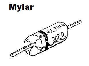
This is a very popular nonpolarized capacitor that is reliable, inexpensive, and has low leakage current but poor temperature stability. Capacitances range from 0.001 to 10 μF, with voltages ratings from 50 to 600 V.

This is an extremely accurate device with very low leakage currents. It is constructed with alternate layers of metal foil and mica insulation, stacked and encapsulated. These capacitors have small capacitance and are often used in high-frequency circuits (e.g., RF circuits). They are very stable under variable voltage and temperature conditions. Tolerances range from +_0.25 to +_5 percent. Capacitance range from 1 pF to 0.01 μF, with maximum voltage ratings from 100 V to 2.5 KV

Variable capacitors are devices that can be made to change capacitance values with the twist of a knob. These devices come in either air-variable or trimmer forms. Air variable capacitors consist of two sets of aluminum plates (stator and rotor) that mesh together but do not touch. Rotating the rotor plates with respect to the stator varies the capacitor’s effective plate surface area, thus changing the capacitance. Air variable capacitors typically are mounted on panels and are used in frequently adjusted tuning applications (e.g., tuning communication receivers over a wide band
of frequencies). A trimmer capacitor is a smaller unit that is designed for infrequent fine-tuning adjustments (e.g., fine-tuning fixed-frequency communications receivers, crystal frequency adjustments, adjusting filter characteristics). Trimmers may use a mica, air, ceramic, or glass dielectric and may use either a pair of rotating plates or a compression-like mechanism that forces the plates closer together.
Reading Capacitor Labels
Reading capacitor labels is tricky business. Each family of capacitors uses its own unique labeling system. Some systems are easy to understand, whereas others make use of misleading letters and symbols. The best way to figure out what a capacitor label means is to first figure out what family the capacitor belongs to. After that, try seeing if the capacitor label follows one of the conventions in the below figure

capacitors, the positive lead must go to the more positive connection; otherwise, it may get zapped as well.
As a practical note, capacitor tolerances can be atrocious. For example, an aluminum electrolytic capacitor’s capacitance may be as much as 20 to 100 percent off the actual value. If an application specifies a low-tolerance capacitor, it is usually safe to substitute a near-value capacitor in place of the specified one.
Reading Capacitor Labels
Reading capacitor labels is tricky business. Each family of capacitors uses its own unique labeling system. Some systems are easy to understand, whereas others make use of misleading letters and symbols. The best way to figure out what a capacitor label means is to first figure out what family the capacitor belongs to. After that, try seeing if the capacitor label follows one of the conventions in the below figure

Important Things to Know about Capacitors
Even though two capacitors may have the same capacitance values, they may have different voltage ratings. If a smaller-voltage capacitor is substituted in place of a higher-voltage capacitor, the voltage level across the replacement may “zap” its dielectric, turning it into a low-level resistor. Also remember that with polarizedcapacitors, the positive lead must go to the more positive connection; otherwise, it may get zapped as well.
As a practical note, capacitor tolerances can be atrocious. For example, an aluminum electrolytic capacitor’s capacitance may be as much as 20 to 100 percent off the actual value. If an application specifies a low-tolerance capacitor, it is usually safe to substitute a near-value capacitor in place of the specified one.
