To make any wire less circuit with less cost we all ways go for RF modules and encoders and decoders .i'm working on HT12E and HT12D.
RF MODULE
As we know that RF communication is better than IR.Range of RF is more than that of IR at the avilable power. Generally an RF module is used for such wireless communication.This RF module comprises of an RF Transmitter and an RF Receiver. The transmitter/receiver (Tx/Rx) pair operates at a frequency of 434 MHz.Other frequencies are also available (but not in the local Indian market). An RF transmitter accepts serial data and transmits it wireless through RF through its antenna connected at pin4. The transmission occurs at the rate of 1Kbps - 10Kbps.The transmitted data is received by an RF receiver operating at the same frequency as that of the transmitter.
We can establish a serial communication between the modules or we can go for encoders at the Tx unit and a decoder at the Rx unit
These are 12 bit encoder and decoder pair available .8bits are assigned for address and 4 bits are for data.There are other pairs available like HT640 encoder ,HT648L decoder(10 bit for address and 8 bit for data).but in Indian market it is hard to find these two.but (HT12E & D) are available every ware.
the pin diagram of the ICs will be as follows
A0 to A7 bits are used for address bits.To achieve proper communication the 8 bit address at the HT12E of transmitter must match with the HT12D at the receiver an external resistor must be connected between "OSC1 & OSC2" for rc oscillator.750Kohm at HT12E and 33Kohm for HT12D.
HT12E has a transmission enable pin (pin 14)which is active low.which must be kept low during transmission.in a similar manner HT12D consisting of Valid transmission pin(pin 17). which goes high on reception of a valid signal from the transmitter.so better to connect an LED for indication but the voltage at this pin may not sufficient to drive an led.so a BC548 transistor can be used. For configuring the address a DIL switch is used.it is an array of switches.
THE CIRCUITS
RF TRANSMITTER: the R2 resistor in the transmitter circuit is of 750Kohm. As this particular value is not available i prefer to use 680Kohm+68Kohm = 748Kohm
PCB LAYOUT OF RF Tx
RF RECEIVER CIRCUIT
RF Rx PCB LAYOUT
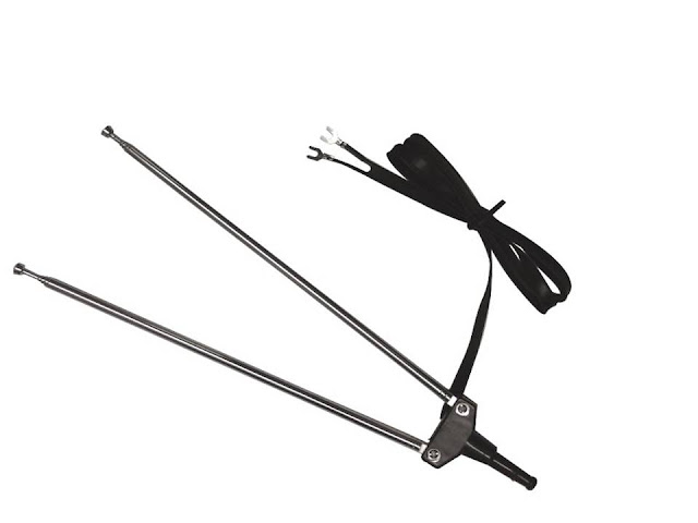
ANTENNA
I prefer to use an old model TV antenna.which is very cheep.i bought it for
38 rupees in an electronics store.it consist two antenna poles.remove the plastic holder and separate the two antennas.so that one can be used at transmitter and other can be used at receiver
while using the RF modules better not to go for supply voltage more than 5v.though for some it may be around 12V.as voltage increases heat desipated fby the module increases.that may cause improper function.


