I all ways wanted to make a quadruped robot. And finally got a chance to make one. So i wanted to simplify the design with least possible hardware.
I checked in the market to get good servos and found these VS-2 servos. These servos provide up to
3Kg-cm torque.
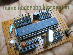
This board consists of an ATmega8 microcontroller working at 16Mhz and almost all the pins are exposed in this board and each and every pin is associated with supply and ground pins.
To load the arduino sketch into this board i made a sketch loader for it. In traditional Arduino boards FTDT chips(FT232) are used. It is a USB to serial devise. I googled about and found a similar chip which is a little cheaper in my local market called CP2102 from silicon lcbs.
#include <Servo.h>
Servo mot1;
Servo mot2;
void setup( )
{
mot1.attach(9); // servo one to digital pin 9 of arduino
mot2.attach(10);// servo two to digital pin 10 of arduino
}
void loop( )
{
mot1.write(60);
mot2.write(120);
delay(300);
mot1.write(120);
mot2.write(60);
delay(300);
}
working video
I checked in the market to get good servos and found these VS-2 servos. These servos provide up to
3Kg-cm torque.
To control the servos i wanted to use ARDUINO. I got Arduino mega with me. But that board is little heavy and my robot cant bare it. So tried for arduino uno or nano. I'm not able to find one in the Indian market and the cost is going beyond the budget. So i thought of making my own Arduino.
This board consists of an ATmega8 microcontroller working at 16Mhz and almost all the pins are exposed in this board and each and every pin is associated with supply and ground pins.
To load the arduino sketch into this board i made a sketch loader for it. In traditional Arduino boards FTDT chips(FT232) are used. It is a USB to serial devise. I googled about and found a similar chip which is a little cheaper in my local market called CP2102 from silicon lcbs.
MECHANICAL ARRANGEMENT

CIRCUIT DIAGRAM:
In this circuit diagram i didn't showed the Power supply for Arduino. if you are using any standard Arduino you have to use a separate 9v supply for your Arduino board. In this project i used an ATmega8L microcontroller(operates from 3.3V to 5V) with Arduino boot-loader. So i used a common power supply for both Board and Motors.
NOTE: if you are using a common supply the circuit may get reset continuously due to more load of motors. To overcome this problem i used 2x1000uF capacitors accross Vcc and Gnd
ARDUINO CODE :
#include <Servo.h>
Servo mot1;
Servo mot2;
void setup( )
{
mot1.attach(9); // servo one to digital pin 9 of arduino
mot2.attach(10);// servo two to digital pin 10 of arduino
}
void loop( )
{
mot1.write(60);
mot2.write(120);
delay(300);
mot1.write(120);
mot2.write(60);
delay(300);
}


when are you gonna start working on the Humanoid?
ReplyDeletesir send me circuit diagram of arduino uno using atmega 8. at rkrai1726@gmail.com
ReplyDeleteHey! can i build this project using my Arduino Uno
ReplyDeletePlease send me the complete document of the project. Thanks
ReplyDeleteOjiakufavour@gmail.com
ReplyDeleteOjiakufavour@gmail.com
ReplyDeleteHi , can i use the Inverse kinematics to code the Robot ?
ReplyDeletevery nice work but what the aim of project monitoring or control???
ReplyDeletecan i use 103 capacitor instead of 2x1000uF capacitor
ReplyDeletePlease send the complete document of this project
ReplyDelete