Every beginner of microcontrollers all ways think of buying a prototyping board for practicing.Why don't you make your own board for working on your projects.I made a simple 8051 development board for prototyping my projects.You can make one by just spending less then 100 rupees.
For that you need very little equipment.
Cut the PCB as per the need of your size of board.First of all take a look at the pin diagram of AT89S52 microcontroller. The EA/VPP(pin 31) must be connected to VCC. The PORT0 must be pulled up through external pullups.So use the 9 pin 10K resistor array for pull up such that common pin to VCC and remaining 8 pins to PORT0 pins.
The power on reset circuit for 8051 will be as shown in the figure
Connection of external ceramic crystal to the AT89S51
arrange all the components as shown in the figure below. step by step
cut the PCB like this
place the 40 pin IC base(i used 42 pin as 40 pin is out of stock)
take some pin heads
place them as per the port pins
and place the remaining required components like crystal,reset circuit,7805 voltage regulator for supply
your home made prototyping board for AT89S51.
for programing the MCU you need a separate ISP programmer.
so many of them are available in the market.
if you use P89V51RD2 microcontroller you just need a max232 IC and a serial cable to program it
For that you need very little equipment.
- pin heads
- 40 pin IC base(i didn't get a 40 pin so i used a 42 pin)
- a 7805 voltage regulator
- crystal (11.0592Mhz or 12.0Mhz as per your requirement)
- 10kohm resistor
- 10kohm resistor 9 pin array
- 10uF electrolytic capacitor
- 33pF disc capacitors
- some connecting wires
- a special PCB that consists of all row holes will be connected
PROCEDURE
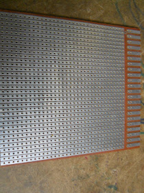
first take a PCB with all its row holes connected as shown in the figureCut the PCB as per the need of your size of board.First of all take a look at the pin diagram of AT89S52 microcontroller. The EA/VPP(pin 31) must be connected to VCC. The PORT0 must be pulled up through external pullups.So use the 9 pin 10K resistor array for pull up such that common pin to VCC and remaining 8 pins to PORT0 pins.
The power on reset circuit for 8051 will be as shown in the figure
Connection of external ceramic crystal to the AT89S51
arrange all the components as shown in the figure below. step by step
cut the PCB like this
place the 40 pin IC base(i used 42 pin as 40 pin is out of stock)
take some pin heads
place them as per the port pins
and place the remaining required components like crystal,reset circuit,7805 voltage regulator for supply
your home made prototyping board for AT89S51.
for programing the MCU you need a separate ISP programmer.
so many of them are available in the market.
if you use P89V51RD2 microcontroller you just need a max232 IC and a serial cable to program it


very nice robo
ReplyDeleteyes
Deleteit is very simple to make your own brain to a robot
"a robot is nothing for an EMBEDDED SYSTEM with wheels"
Awesome project..!
ReplyDeletei am making a grid follower.. so i wanted to know how many sensors should i use for it ?
it would be really really helpful is you can contact me on my email : ayush.srivastav@yahoo.com
that depends upon your design for detecting a line you must use minimum 2 sensors refer to the basic line follower article.
ReplyDeletethe sensitivity of the robot depends on the number of sensors.
some people use line sensor arrays for more accuracy.
what is the use of pull up resistors on the port 0?
ReplyDeletePort O doesn't have internal pull ups so we connect external ones. It is used to keep the signal pin not to get tri-stated or you can say a voltage that is neither logic 1 nor logic 0
Delete