Friday 30 March 2012

RESISTOR color coding

Every  newbie of electronics must be aver of some fundamental.Knowing the "resistor" is one of that.
the question is"what is resistor ?what is getting resisted?

Every one knows that "current" is nothing but flow of electrons just like water flow through a pipe.
here pipe means any conducting wire.The operation of pump is similar to that of a battery.Tap is nothing but a switch in the circuit
look at the following image


measure of resistance:
In the water pipeline the narrow neck opposes the water flow.Similarly the resistor opposes the flow of current in the conducting wire.

The resistance(R) of a material will be proportional to it's length(L)
 and inversely proportional to it's cross sectional area(A).
Considering the constant of proportionality (p) called resistivity.


In this formula, length and area are geometric properties of the cylinder; the ratio L/A has dimensions of reciprocal length. The Greek symbol "rho" above stands for resistivity, a property of the material making up the cylinder, usually reported in ohm-cm. The separation of the dependence of a physical quantity into geometric and material parts is typical.

we cannot use a resistor of more length in our circuits so we use resistors of different materials are available in several sizes.


how to find the resistance of a resistor?
the ordinary resistor we use in the laboratory consist of a color coding on it.depending upon the color band pattern printed on it we can find the resistance.look at the figure below


consider the following example:
above resistor is of 4-band color type.so the resistance calculation will be as follows

                                yellow        violet              red             gold
                                   4                7                10^2           +-5%

                                         R= 4700 ohm = 4.7 K ohm


Wednesday 28 March 2012

HEAVY DUTY ROBOT RACER WITH WIRELESS CONTROL

we all participate in robotic competitions even i did
i lost my first racing competition because of lesser power motor and in efficient driver circuit.
i worked on it a lot and finally found some solutions.

solution1:  use metal geared motor instead of plastic gear (i lost my match because of plastic motors)
                  and wheel of maximum possible grip.

solution 2:  use proper motor driving technique.

solution3:  make strong chases with light weight with maximum possible ground clearance.

solution4:  use proper battery with less size and more power that works for longer period.

solution5:  better to be wireless

i made a prototype of my own racer.this racer can reach 15Km/h
it can carry up to 4kg of load
actually i made it for carrying a robot arm, gun platform and a video camera


Using this platform i made a robot gun tank.

Now a day’s security plays crucial role in any country. So many soldiers are sacrificing their lives for the sake of the country. But the technology is changing day by day. A new area began in the field of science. That is ROBOTICS. Several researches were under taken in the field of robotics. Robots are being used in different fields where there is a difficulty to the humans. Robots can be used even in the field of defense. If we lose a robot we can replace it with another one but we cannot replace a soldier with another.
Many countries started using robots in the wars. For example USA recently developed a robot called SWARD which can carry a rifle and fire at the destined targets. We tried to make a robot that will be faster enough to serve the soldiers in the battle field.
We implemented this project using two micro controllers 8051 at the transmitter and ATmega16L at the receiver. The robot platform is based on the high performance Jonson-H motors. This robot can be operated through remote through RF communication by using encoder and decoder at the transmitter and receiver with 8bit secured address. This kind of robots helps the soldiers by making some modifications in the robot we can make it to carry the goods at the battle fields to help the soldiers.
for base motors high power metal  gear motors are used


Motor ratings:

1000RPM 12V DC geared motors for robotics applications. It gives a massive torque of 12Kgcm. The motor comes with metal gearbox and off-centered shaft. Shaft has a metal bushing for wear Resistance.
Features
  • 1000RPM 12V DC motors with Metal Gearbox
  • 18000 RPM base motor
  • 6mm shaft diameter
  • Gearbox diameter 37 mm.
  • Motor Diameter 28.5 mm
  • Length 63 mm without shaft
  • Shaft length 15mm
  • 300gm weight
  • 12kgcm torque
  • No-load current = 800 mA(Max),
  •  Load current = upto 9.5 A(Max)
a special motor driver circuit is designed using relays for driving motors at high currents
when there is no current flowing in the coil the switch will be as shown in the figure.that means in normal state there will be connection between "common" and "contact". when ever current is flowing in the coil the core is magnetized and attracts the switch.so the switch will be moved towards "non contact". so a connection will be established between "NC" and "CM".
 for driving a motor we need two relays
the circuit for connecting relays will be as follows.
the following circuit is a high current motor driver using relays.

actually we are implementing a H-bridge using the relays. when ever a logic "1" is applied to the transistor base then the corresponding relay will be activated .it will be very simple mechanism. if you are using more than one motor i prefer you to use a ULN2003 IC for driving relays.one ULN2003 can drive "7" relays.
so that you can control "3" motors with still one left.if you use two ICs you can control "7" motors.
these relays can drive very large currents compared to L293D and L298   

i made a perfect robot that will help you in racing..... take a look at it


for wireless circuit refer the 434 MHz RF modules circuit

Monday 26 March 2012

STEPPER MOTOR basic

STEPPER MOTOR
Stepper motors, or steppers, are digitally controlled brushless motors that rotate a specific number of degrees (a step) every time a clock pulse is applied to a special translator circuit that is used to control the stepper. The number of degrees per step (resolution) for a given stepper motor can be as small as 0.72° per step or as large as 90° per step. Common general-purpose stepper resolutions are 15 and 30° per step.
Unlike RC servos, steppers can rotate a full 360° and can be made to rotate in a continuous manner like a dc motor (but with a lower maximum speed) with the help of proper digital control circuitry. Unlike dc motors, steppers provide a large amount of torque at low speeds, making them suitable in applications where low-speed and high-precision position control is needed. For example, they are used in printers to
control paper feed and are used to help a telescope track stars. Steppers are also
found in plotter- and sensor-positioning applications. The list goes on. To give you a
basic idea of how a stepper works, take a look at the Figure.

Here is a simple model depicting a 15° per step variable-reluctance stepper.The stationary section of the motor, called the stator, has eight poles that are spaced 45° apart. The moving section of the motor, called the rotor, is made from a ferromagnetic material (a material that is attracted to magnetic fields) that has six teeth spaced 60° apart.To make the rotor turn one step, current is applied, at the same time, through two opposing pole pairs, or coil pairs.The applied current causes the opposing pair
of poles to become magnetized. This in turn causes the rotor’s teeth to align with the poles, as shown in the figure.To make the rotor rotate 15° clockwise from this position, the current through coil pair 1 is removed and sent through coil pair 2.To make the rotor rotate another 15° clockwise from this position, the current is removed from coil pair 2 and sent through coil pair 3.The process continues in this way.To make the rotor spin counterclockwise, the coil-pair firing sequence is reversed.

TYPES OF STEPPER MOTORS

The model used in the last example was based on a variable-reluctance stepper. As it turns out, this model is incomplete—it does not show how a real variable-reluctance stepper is wired internally. Also, the model does not apply to a class of steppers referred to as permanent-magnet steppers. To make things more realistic, let’s take a look at some real-life steppers

This figure shows a physical model and schematic diagram of a 30° per step variable reluctance stepper. This stepper consists of a six-pole
(or three-coil pair) stator and a
four-toothed ferromagnetic rotor. Variable-reluctance steppers with higher angular resolutions are constructed with more coil pairs and/or more rotor teeth. Notice that
in both the physical model and the schematic, the ends of all the coil pairs are joined together at a common point. (This joining of the coil ends occurs internally within the
motor’s case.) The common and the coil pair free ends are brought out as wires from the motor’s case. These wires are referred to as the phase wires. The common wire is connected to the supply voltage, whereas the phase wires are grounded in sequence according to the table shown below.


UNI-POLAR STEPPER MOTOR

These steppers have a similar stator arrangement as the variable-reluctance steppers, but they use a permanent-magnet rotor and different internal wiring arrangements.Figure shows a 30° per step unipolar stepper. Its consists of a four-pole (or two coil pair) stator with center taps between coil pairs and a six-toothed permanent magnetic rotor. The center taps may be wired internally and brought out as one wire
or may be brought out separately as two wires. The center taps typically are wired to the positive supply voltage, whereas the two free ends of a coil pair are alternately grounded to reverse the direction of the field provided by that winding. As shown in the figure, when current flows from the center tap of winding 1 out terminal 1a, the top stator pole “goes north,” while the bottom stator pole “goes south.” This causes the rotor to snap into position. If the current through winding 1 is removed, sent through winding 2, and out terminal 2a, the horizontal poles will become energized, causing the rotor will turn 30°, or one step. In Fig , three firing sequences are shown. The first sequence provides full stepping action (what I just discussed). The second sequence, referred to as the power stepping sequence, provides full stepping
action with 1.4 times the torque but twice the power consumption. The third sequence provides half stepping (e.g., 15° instead of the rated 30°). Half stepping is made possible by energizing adjacent poles at the same time. This pulls the rotor in between the poles, thus resulting in one-half the stepping angle. As a final note,
unipolar steppers with higher angular resolutions are constructed with more rotor teeth. Also, uni polars come in either five- or six-wire types. The five-wire type has the center taps joined internally, while the six-wire type does not.


BIPOLAR STEPPER MOTOR


These steppers resemble unipolar steppers, but their coil pairs do not have center taps. This means that instead of simply supplying a fixed supply voltage to a lead, as was
the case in unipolar steppers (supply voltage was fixed to center taps), the supply voltage must be alternately applied to different coil ends. At the same time, the opposite end of a coil pair must be set to the opposite polarity (ground). For example, in
 Figure, a 30° per step bipolar stepper is made to rotate by applying the polarities shown in the firing sequence table to the leads of the stepper. Notice that the firing sequence
uses the same basic drive pattern as the unipolar stepper, but the “0” and “1” signals are replaced with “+” and “−” symbols to show that the polarity matters. As you will see in the next section, the circuitry used to drive a bipolar stepper requires an
H-bridge network for every coil pair.  Bipolar steppers are more difficult to control than both uni polar steppers and variable-reluctance steppers, but their unique polarity-shifting feature gives them a better size-to-torque ratio. As a final note, bipolar
steppers with higher angular resolutions are constructed with more rotor teeth.


UNIVERSAL STEPPER MOTOR


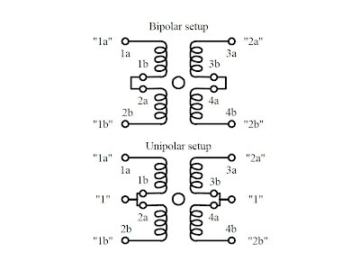
These steppers represent a type of unipolar-bipolar hybrid. A universal stepper comes with four independent windings and eight leads. By connecting the coil windings in parallel, as shown in Figure, the universal stepper can be converted into a
unipolar stepper. If the coil windings are connected in series, the stepper can be converted into a bipolar stepper.


"WHAT EVER THE TYPE OF STEPPER IS TO ROTATE IT THE BASIC LOGIC IS TO


 CONNECT THE CENTER TAPS OF THE COILS TO POSITIVE TERMINAL OF SUPPLY 


AND THE REMAINING ENDS OF COILS MUST BE GROUNDED(CONNECTED TO 


NEGATIVE TERMINAL OF THE SUPPLY) IN THE ORDER DISCUSSED ABOVE"

  
for this "grounding" several techniques are used.but the main role of such devise will be"SWITCHING" the motor coils
the arrange ment will be


but we need a devise to perform the switching operation for that i prefer the following ULN2003 it consists of 7 darlington array.refer the data sheet for more


the over all arrangement will be as follows
 

connect the in1,in2,in3,in4 pins of 2003 to the control logic
and follow the algorithm as per the type of motor

Sunday 25 March 2012

PCB designing with EAGLE


if you are a beginner in PCB designing i prefer EAGLE  
this is the best software that helps to design PCB s for beginners

this is my first schematic of 8051 board  


PCB layout of above schematic 


main motto of any PCB designer will be:
                              TO DESIGN A PCB WITH LEAST POSSIBLE SIZE


Saturday 24 March 2012

how to work with keil


video on working with keil 


Thursday 22 March 2012

HOW TO CONVERT DC MOTOR INTO SERVO MOTOR

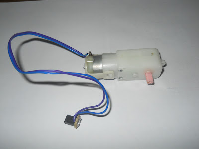
Working with servos is a bit costly so i all ways think about conversion of a ordinary DC motor into a servo motor.in a servo motor it consists of a rotatory encoder connected to the shaft of motor for position feed backall optical rotatory encoder are a bit costly. in my looo.....ong search of a cheep encoder i found one
guess what??????????????????????
                                                   POTENTIOMETER(POT) 


all of us familiar with this potentiometer.which act as a potential divider between three points.
it consists of three pins.the resistance between pins 1 and 3 is constant. but if we rotate the shaft then resistance between (1,2) or (2,3) varies.the center pin some times referred as wiper.    


   MAKING:
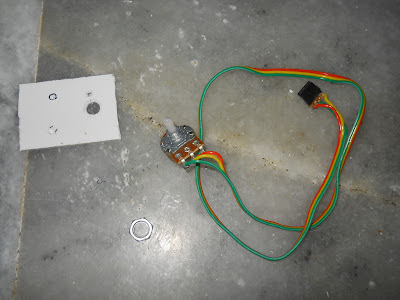
  take a10k pot and solder three wires to it as shown in the picture 


BLACK== GND, BROWN == O/PRED==Vcc

FOLLOW THE IMAGES


OVER ALL BLOCK DIAGRAM


PSEUDO CODE LOGIC:

main()
{
   config adc;

  config motor control pins;
 
   while(1)
  {
     read adc of control pot;
    read adc of motor pot;
    if(motor adc > control adc)
       motor forward;                            // could also be back ward
     else if( motor adc < control adc)  //the idea is to turn motor in direction than neutralizes                           motor back ward ;                    //error  between motor pot value and control pot value
     else
       motor stop;      // if no error motor stop
   }

}